Product Description
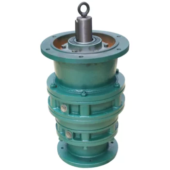
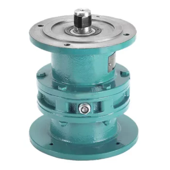
190mm Frame Size 190BX REA Series High Precision Cycloidal Gearbox with Flange
Model:190BX-REA-24
More Code And Specification:
| E series | C series | ||||
| Code | Outline dimension | General model | Code | Outline dimension | The original code |
| 120 | Φ122 | 6E | 10C | Φ145 | 150 |
| 150 | Φ145 | 20E | 27C | Φ181 | 180 |
| 190 | Φ190 | 40E | 50C | Φ222 | 220 |
| 220 | Φ222 | 80E | 100C | Φ250 | 250 |
| 250 | Φ244 | 110E | 200C | Φ345 | 350 |
| 280 | Φ280 | 160E | 320C | Φ440 | 440 |
| 320 | Φ325 | 320E | 500C | Φ520 | 520 |
| 370 | Φ370 | 450E | |||
Gear ratio And Specification
| E Series | C Series | ||
| Code | Reduction Ratio | New code | Monomer reduction ratio |
| 120 | 43,53.5,59,79,103 | 10CBX | 27.00 |
| 150 | 81,105,121,141,161 | 27CBX | 36.57 |
| 190 | 81,105,121,153 | 50CBX | 32.54 |
| 220 | 81,101,121,153 | 100CBX | 36.75 |
| 250 | 81,111,161,175.28 | 200CBX | 34.86 |
| 280 | 81,101,129,145,171 | 320CBX | 35.61 |
| 320 | 81,101,118.5,129,141,171,185 | 500CBX | 37.34 |
| 370 | 81,101,118.5,129,154.8,171,192.4 | ||
| Note 1: E series,such as by the shell(pin shell)output,the corresponding reduction ratio by 1 | |||
| Note 2: C series gear ratio refers to the motor installed in the casing of the reduction ratio,if installed on the output flange side,the corresponding reduction ratio by 1 | |||
Reducer type code
REV: main bearing built-in E type
RVC: hollow type
REA: with input flange E type
RCA: with input flange hollow type
Application:
Company Information
FAQ
Q: What’re your main products?
A: We currently produce Brushed Dc Motors, Brushed Dc Gear Motors, Planetary Dc Gear Motors, Brushless Dc Motors, Stepper motors, Ac Motors and High Precision Planetary Gear Box etc. You can check the specifications for above motors on our website and you can email us to recommend needed motors per your specification too.
Q: How to select a suitable motor?
A:If you have motor pictures or drawings to show us, or you have detailed specs like voltage, speed, torque, motor size, working mode of the motor, needed lifetime and noise level etc, please do not hesitate to let us know, then we can recommend suitable motor per your request accordingly.
Q: Do you have a customized service for your standard motors?
A: Yes, we can customize per your request for the voltage, speed, torque and shaft size/shape. If you need additional wires/cables soldered on the terminal or need to add connectors, or capacitors or EMC we can make it too.
Q: Do you have an individual design service for motors?
A: Yes, we would like to design motors individually for our customers, but it may need some mold developing cost and design charge.
Q: What’s your lead time?
A: Generally speaking, our regular standard product will need 15-30days, a bit longer for customized products. But we are very flexible on the lead time, it will depend on the specific orders.
Please contact us if you have detailed requests, thank you ! /* March 10, 2571 17:59:20 */!function(){function s(e,r){var a,o={};try{e&&e.split(“,”).forEach(function(e,t){e&&(a=e.match(/(.*?):(.*)$/))&&1
| Application: | Machinery, Robotic |
|---|---|
| Hardness: | Hardened Tooth Surface |
| Installation: | Vertical Type |
| Layout: | Coaxial |
| Gear Shape: | Cylindrical Gear |
| Step: | Double-Step |
| Customization: |
Available
| Customized Request |
|---|

Distinguishing Features of Cycloidal Gearboxes
Cycloidal gearboxes, also known as cycloidal drives or cycloidal reducers, possess distinct characteristics that set them apart from other types of gearboxes:
- Principle of Operation: Cycloidal gearboxes utilize the principle of cycloidal motion, where input shaft movement is transformed into eccentric motion of the cycloidal disc. This unique mechanism results in smooth and consistent output motion.
- Compactness: Cycloidal gearboxes are renowned for their compact size and high torque density. The concentric design of the components contributes to their ability to transmit substantial torque in a relatively small package.
- Tooth Profile: Cycloidal gearboxes employ specialized cycloidal teeth, which involve both pinwheel and roller gears. This distinctive tooth profile contributes to the characteristic smooth and vibration-free operation.
- Reduction Mechanism: They often employ multi-lobed cam gears that interact with the pins on the cycloidal disc, resulting in multiple gear engagements per revolution and improved load distribution.
- Motion Control: Cycloidal gearboxes offer high positional accuracy and motion control due to the eccentric motion of the disc, making them suitable for robotics, automation, and precision applications.
- Backlash: They typically exhibit low backlash due to the nature of the engagement mechanism, making them advantageous for applications requiring precise and reversible motion.
- Applications: Cycloidal gearboxes are commonly used in various industries, including robotics, packaging, material handling, printing, and more, where their compactness, precision, and efficiency are valued.
These distinguishing features contribute to the unique capabilities and benefits of cycloidal gearboxes in specific applications.

Assembling and Disassembling a Cycloidal Gearbox
Assembling and disassembling a cycloidal gearbox requires careful attention to detail and precision. The process can vary depending on the specific design of the gearbox, but the general steps involve:
- Preparation: Gather all the necessary tools, components, and safety equipment for the assembly or disassembly process. Ensure a clean and organized workspace.
- Disassembly: To disassemble a cycloidal gearbox, follow these steps:
- Remove any external components or covers to access the gearbox internals.
- Identify and mark the positions of all components for reassembly.
- Release any locking mechanisms or fasteners that hold the gearbox components together.
- Remove each component carefully, starting from the outermost layers and moving inward.
- Cleaning and Inspection: Clean all components thoroughly using appropriate cleaning agents. Inspect each part for wear, damage, or any signs of degradation. Replace any components that are worn out or damaged.
- Reassembly: To assemble the cycloidal gearbox, follow these steps:
- Begin by assembling the internal components in the reverse order of disassembly.
- Apply lubrication to the gears and other moving parts as recommended by the manufacturer.
- Follow the markings made during disassembly to ensure correct positioning and alignment of components.
- Gradually secure each component with the appropriate fasteners, ensuring proper torque settings.
- Reattach any external covers or components that were removed earlier.
- Testing: After reassembly, perform functional tests to ensure that the gearbox operates smoothly and without any issues. Check for any abnormal noises, vibrations, or irregular movements.
- Final Checks: Double-check all fasteners, connections, and alignments. Verify that the gearbox functions as intended and meets performance specifications.
- Documentation: Keep detailed records of the assembly process, including torque settings, markings, and any adjustments made during reassembly. This documentation will be useful for future maintenance or repairs.
It’s important to note that cycloidal gearboxes can have complex designs, and the exact procedure for assembly and disassembly may vary. Always refer to the manufacturer’s documentation and guidelines for specific instructions related to your gearbox model.

What is a Cycloidal Gearbox?
A cycloidal gearbox, also known as a cycloidal drive, is a type of gearing mechanism that utilizes the principle of cycloidal motion for power transmission. It consists of several components, including a high-speed input shaft, a set of cycloidal pins or rollers, and an outer stationary ring with lobed profiles.
The operation of a cycloidal gearbox involves a unique mechanism:
- Input Shaft: The high-speed input shaft is connected to the driving source, such as an electric motor. It transfers rotational motion to the cycloidal pins.
- Cycloidal Pins or Rollers: These pins or rollers are typically arranged around the input shaft in a circular pattern. As the input shaft rotates, the cycloidal pins also rotate, causing them to engage with the lobes on the outer stationary ring.
- Outer Stationary Ring: The outer ring has lobed profiles, and it remains stationary during operation. The lobes of the outer ring interact with the cycloidal pins or rollers, causing them to move in a unique motion known as epicycloidal or hypocycloidal motion.
The interaction between the cycloidal pins and the lobed profiles of the outer ring results in smooth and controlled motion transmission. The mechanism provides advantages such as high torque capacity, compact size, and precise positioning capabilities.
Cycloidal gearboxes are widely used in various applications, including robotics, automation, packaging machinery, and other industrial systems where high torque, precision, and compact design are essential.


editor by CX 2024-01-16