Product Description
Overview
Quick Details
| Video outgoing-inspection: Provided
|
Machinery Test Report: Provided
|
| Marketing Type:New Product 2571
|
Warranty of core components:
More than 5 years |
| Applicable Industries: Manufacturing Plant
|
bush: bearing bush
|
| the pressure lid: 0.6~0.8MPa
|
Mixing chamber: Abrasion resistance
|
| the rotors: chroming carbide alloy
|
Showroom Location:
Canada, Turkey, United Kingdom, United States, Viet Nam, Brazil, Peru, Saudi Arabia, Indonesia, Mexico, Russia, Thailand, Argentina, Chile, Sri Lanka, Ukraine, Uzbekistan, Japan, Malaysia |
| After Warranty Service:Spare parts
|
Certification: CE/SGS/ISO
|
| control: PLC | Motor and reducer:Strengthened model
|
| Core Components:
PLC, Engine, Bearing, Gearbox, Motor, Gear, Pump |
Dimension(L*W*H):
3330*2620*3340mm |
| Voltage:
220v,240v,380v,400v,415v,440v |
Key Selling Points:
High Productivity |
| Warranty:
More than 5 years |
Weight (KG):
10500 KG |
| Power (kW):
110 kW |
After-sales Service Provided:
Engineers available to service machinery overseas |
| simple structure:
easy operation |
Type:
Rubber Kneader |
Supply Ability
Supply Ability
30 Set/Sets per Month
Packaging & Delivery
Packaging Details
Standard exported package ,FCL or according to your requirement.
Port
HangZhou port or any port of China
75L Stronger power plastics banbury mixer / PE dispersion mixer / PVC dispersion kneader
High safety factor,low energy cost, high degree of production sanitation
Brief description
1.Excellent sealing performance(copper sealing ring)
2.No leakage of powder /oil-proof
3.Automatic and manual interaction
4.Rotors:chroming carbide alloy ,15 silk
5.Type of rotors:standard two-wing tangential rotor ,four-wing synchronous rotor ,welded up alloy rotor and cylindrical intermeshing rotor
Laboratory banbury mixer
Mixing chamber:
It consists of a “W” shape body and 2 side boards made of high quality steel plates by means of extrusion forming and welding, which are jacked to take the flow of cooling water or steam. It is plated with hard chrome on its internal walls.
Thermal Resistance:
There is a plug-in thermal resistance in middle section of the bottom of the chamber to be connected to electrical system to inspect and display the temperate.
The rotors:
It is designed to the hollow blades of Banbury type. The hollows are connected with axial hole of rotor shaft used as cooling or heating passage. The top edges of blades and the end faces of ~ rotor shaft are surface welded with cobalt-base hard alloy and grinding, then plating with hard chrome and polishing.
Cooling/heating system:
A common piping system is used .Cooling water/steam/medium oil is led in 3 ways into the cavities of the rotor CZPT ,the mixing chamber and the ram to cool or heat stock in a circulation way.
Tilting mechanism:
It consists of a rotor with brake, cycloidal gear reducer, TP type worm and worm gear, etc.. It is able to actuate the mixing chamber tilting by 140° around the front rotors.
Dust sealing device:
At the joint between the top of the mixing chamber and the cantilevered arm of the machine frame, the dust sealing assemblies with curved slotted partings are used obtaining an excellent and reliable sealing purpose.
The end face of the rotor is sealed by end contact sealing with nor oil-lubrication and is seals well and is wear-resistant and durable.
Main driving system:
It is comprised of the main motor,the speed reducer and the connecting gearbox to drive the 2 rotor shafts rotatingat differential or same speed in oppsite directions.
Pneumatic control system:
The PLC commands the bid-directional cylinder to drive the ram going up and down.In case the mixing is over load,the ram floats up automatically to protect the motor from operation at over load.The ram can be forcibly lifted manually ,if necessary.
Technical parameter:
|
Model |
X(S)N-20*34 |
X(S)N-35*30 |
X(S)N-55*30 |
X(S)N-75*30 |
X(S)N-110*30 |
|
Total Volume (L) |
45 |
75 |
125 |
175 |
250 |
|
Working Volume (L) |
20 |
35 |
55 |
75 |
110 |
|
Power(KW) |
30 |
55 |
75 |
110 |
185 |
|
Tilting Power(KW) |
1.5 |
2.2 |
2.2 |
3.0 |
7.5 |
|
Tilting Angle |
140° |
140° |
140° |
140° |
140° |
|
Rotational Speed (r/min) |
34/28 |
30/24.5 |
30/24.5 |
30/24.5 |
30/24.5 |
|
Size(mm) |
3100*1300*2450 |
3200*1900*2945 |
3300*1900*2900 |
3760*2143*3135 |
4075*2712*3580 |
Specifications:
1. The plastic material in airtight plastic pressure under the condition of refining or mixed refine, high production efficiency, low labor strength, stable quality. The 2 edges rotor shearing type, the production process the plastic materials that can be fully tear make the material shear well reach dispersion and evenness.
2. The edges of the rotor CZPT surfacing wear-resisting hard alloy, and mixing rubber room and material part of the contact all use hard chromium plating fine polishing processing. Mixed refine chamber adopts clip set of type structure, can be out water/steam/medium oil, have good cooling or heating effect, adapt to all kinds of refined rubber refining technological requirements of the plastic.
3. From the back door charging, mixing rubber room maximum flip 140 ° CZPT unloading, and according to the customer requirement of process can be arbitrary regulation Angle, facilitate next process of connection.
4. The switch on the “w” type, facilitate materials can be fully mixing rubber or refining.
5. The electric control system the programmable logic controller (PLC), has the alarm, unloading
operation, manual/automatic conversion, chain security protection function.
Term of shipment
OUR PRODUCT:
FAQ
| After-sales Service: | Technical Support |
|---|---|
| Warranty: | 6 Month |
| Application: | Hardware |
| Customization: |
Available
| Customized Request |
|---|
.shipping-cost-tm .tm-status-off{background: none;padding:0;color: #1470cc}
| Shipping Cost:
Estimated freight per unit. |
about shipping cost and estimated delivery time. |
|---|
| Payment Method: |
|
|---|---|
|
Initial Payment Full Payment |
| Currency: | US$ |
|---|
| Return&refunds: | You can apply for a refund up to 30 days after receipt of the products. |
|---|

The Basics of a Cyclone Gearbox
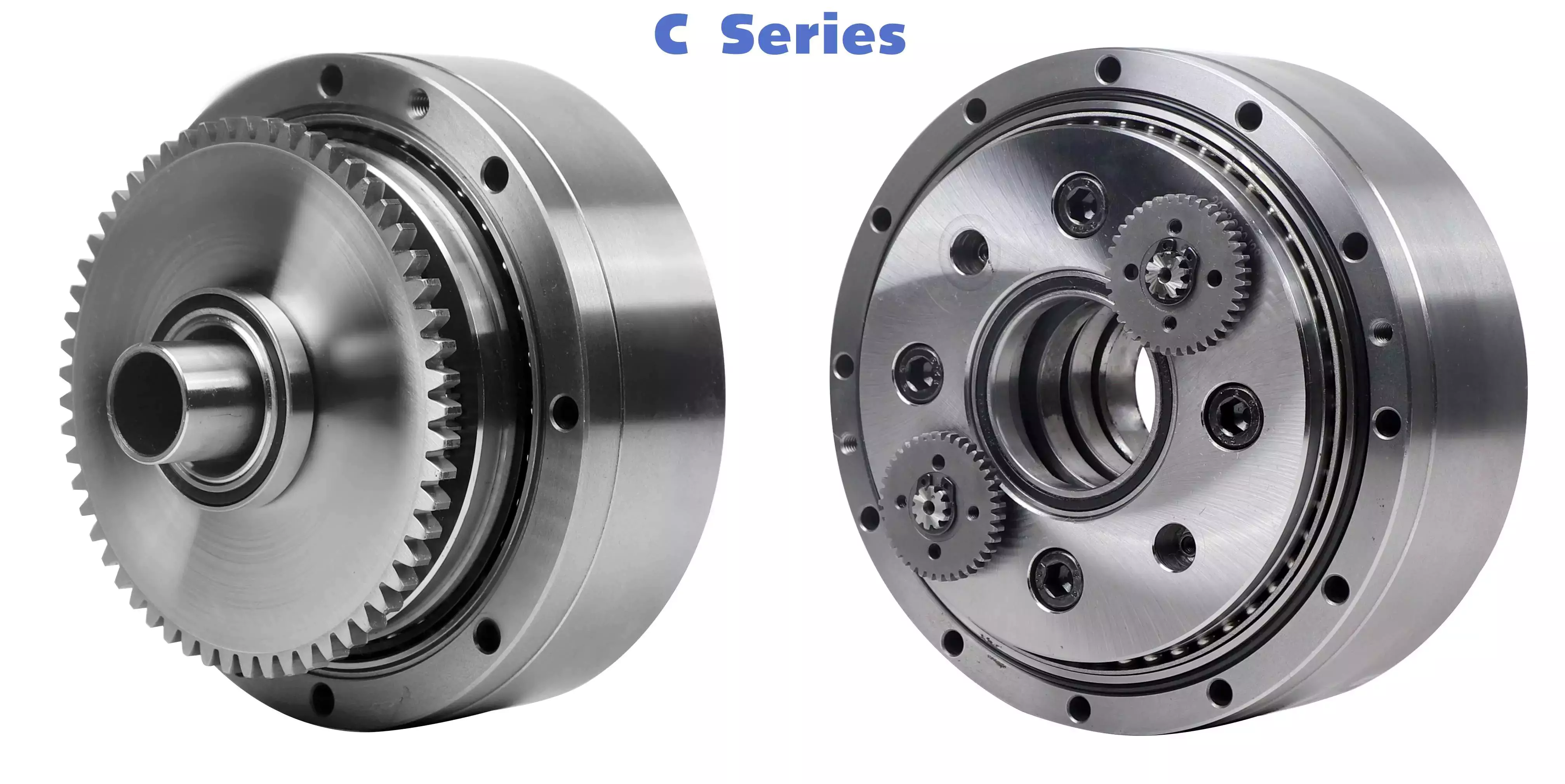
Besides being compact, cycloidal speed reducers also offer low backlash and high ratios. Because of the small size of the drive, they are ideal for applications where space is a problem.
Involute gear tooth profile
Almost all gears use an involute gear tooth profile. This profile has a single curve, which means that the gear teeth do not have to be aligned closely with each other. This profile is smooth and can be manufactured easily.
Cycloid gears have a combination of epicycloid and hypocycloid curves. This makes them stronger than involute gear teeth. However, they can be more expensive to manufacture. They also have larger reduction ratios. They transmit more power than involute gears. Cycloid gears can be found in clocks.
When designing a gear, you need to consider several factors. Some of these include the number of teeth, the tooth angle and the lubrication type. Having a gear tooth that is not perfectly aligned can result in transmission error, noise and vibration.
The tooth profile of an involute gear is usually considered the best. Because of this, it is used in a wide variety of gears. Some of the most common applications for this profile are power transmission gears. However, this profile is not the best for every application.
Cycloid gears require more complex manufacturing processes than involute gear teeth. This can cause a larger tooth cost. Cycloid gears are used for less noisy applications.
Cycloid gears also transmit more power than involute gears. This can cause problems if the radii change tangentially. However, the shape is more simple than involute gears. Involute gears can handle centre sifts better.
Cycloid gears are less susceptible to transmission error. Cycloid gears have a convex surface, which makes them stronger than involute teeth. Cycloid gears also have a larger reduction ratio than involute gears. Cycloid teeth do not interfere with the mating teeth. However, they have a smaller number of teeth than involute teeth.
Rotation on the inside of the reference pitch circle of the pins
Whether a cycloidal gearbox is designed for stationary or rotating applications, the fundamental law of gearing must be observed: The ratio of angular velocities must be constant. This requires the rotation on the inside of the reference pitch circle of the pins to be constant. This is achieved through a series of cycloidal teeth, which act like tiny levers to transmit motion.
A cycloidal disc has N lobes which are rotated by three lobes per rotation around N pins. The number of lobes on a cycloidal disc is a significant factor in determining the transmission ratio.
A cycloidal disc is driven by an eccentric input shaft which is mounted to an eccentric bearing within an output shaft. As the input shaft rotates, the cycloidal disc moves around the pins of the pin disc.
The drive pin rotates at a 40 deg angle while the cycloidal disc rotates on the inside of the reference pitch circle of pins. As the drive pin rotates, it will slow the output motion. This means that the output shaft will complete only three revolutions with the input shaft, as opposed to nine revolutions with the input shaft.
The number of teeth on a cycloidal disc must be small compared to the number of surrounding pins. The disc must also be constructed with an eccentric radius. This will determine the size of the hole which will be required for the pin to fit between the pins.
When the input shaft is turned, the cycloidal disc will rotate on the inside of the reference pitch circle of roller pins. This will then transmit motion to the output shaft. The output shaft is supported by two bearings in an output housing. This design has low wear and torsional stiffness.
Transmission ratio
Choosing the right transmission ratio of cycloidal gearbox isn’t always easy. You might need to know the size of your gearbox before you can make an educated choice. You may also need to refer to the product catalog for guidance. For example, CZPT gearboxes have some unique ratios.
A cycloidal gear reducer is a compact and high-speed torque transmission device that reverses the direction of angular movement of the follower shaft. It consists of an eccentric cam positioned inside a cycloidal disc. Pin rollers on the follower shaft fit into matching holes in the cycloidal disc. In the process, the pins slide around the holes, in response to wobbling motion. The cycloidal disc is also capable of engaging the internal teeth of a ring-gear housing.
A cycloidal gear reducer can be used in a wide variety of applications, including industrial automation, robotics and power transmissions on boats and cranes. A cycloidal gear reducer is ideally suited for heavy duty applications with large payloads. They require specialized manufacturing processes, and are often used in equipment with precise output and high efficiency.
The cycloidal gear reducer is a relatively simple structure, but it does require some special tools. Cycloid gear reducers are also used to transmit torque, which is one of the reasons they are so popular in automation. Using a cycloidal gear reducer is a good choice for applications that require higher efficiency and lower backlash. It is also a good choice for applications where size is a concern. Cycloid gears are also a good choice for applications where high speed and high torque are required.
The transmission ratio of cycloidal gearbox is probably the most important function of a gearbox. You need to know the size of your gearbox and the type of gears it contains in order to make the right choice.
Vibration reduction
Considering the unique dynamics of a cycloidal gearbox, vibration reduction measures are required for a smooth operation. These measures can also help with the detection of faults.
A cycloidal gearbox is a gearbox with an eccentric bearing that rotates the center of the gears. It shares torque load with five outer rollers at any given time. It can be applied in many applications. It is a relatively inexpensive asset. However, if it fails, it can have significant economic impacts.
A typical input/output gearbox consists of a ring plate and two cranks mounted on the input shaft. The ring plate rotates when the input shaft rotates. There are two bearings on the output shaft.
The ring plate is a major noise source because it is not balanced. The cycloidal gear also produces noise when it meshes with the ring plate. This noise is generated by structural resonance. Several studies have been performed to solve this problem.
However, there is not much documented work on the condition monitoring of cycloidal gearboxes. In this article, we will introduce modern techniques for vibration diagnostics.
A cycloidal gearbox with a reduced reduction ratio has higher induced stresses in the cycloidal disc. In this case, the size of the output hole is larger and more material is removed from the cycloidal disc. This increase in the disc’s stresses leads to higher vibration amplitudes.
The load distribution along the width of the gear is an important design criterion. Using different gear profiles can help to optimize the transmission of torque. The contact stress of the cycloidal disc can also be investigated.
To determine the amplitude of the noise, the frequency of the gear mesh is multiplied by the shaft rate. If the RPM is relatively stable, the frequency can be used as a measure of magnitude. However, this is only accurate at close to failure.
Comparison with planetary gearboxes
Several differences exist between cycloidal gearboxes and planetary gearboxes. They are related to gear geometry and manufacturing processes. Among them, there are:
– The output shaft of a cycloidal gearbox has a larger torque than the input shaft. The rotational speed of the output shaft is lower than the input shaft.
– The cycloid gear disc rotates at variable velocity, while the planetary gear has a fixed speed. Consequently, the cycloid disc and output flange transmission accuracy is lower than that of the planetary gears.
– The cycloidal gearbox has a larger gripping area than the planetary gear. This is an advantage of the cycloidal gearbox in that it can handle larger loads.
– The cycloid profile has a significant impact on the quality of contact meshing between the tooth surfaces. The width of the contact ellipses increases by 90%. This is a result of the elimination of undercuts of the lobes. In this way, the contact force on the cycloid disc is decreased significantly.
– The cycloid drive has lower backlash and high torsional stiffness. This allows a cycloidal drive to be more stable against shock loads. The cycloid drive is also a compact design, which is ideally suited for applications with large transmission ratios.
– The output hub of the cycloid gearbox has movable pins and rollers. These components are attached to the ring gear in the outer gearbox. The output shaft is also turned by the planet carrier. The output hub of the cycloid system is composed of two parts: the ring gear and the output flange.
– The input shaft of a cycloidal gearbox is connected to a servomotor. The input shaft is a cylindrical element that is fixed to the planet carrier.

editor by CX 2023-11-08