Product Description
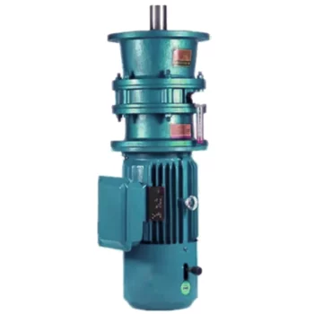
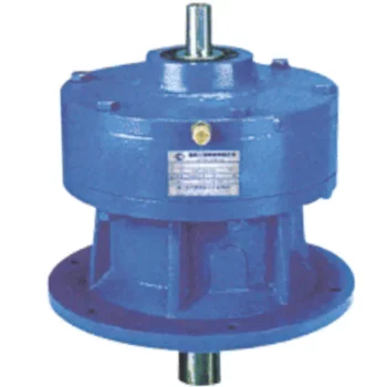
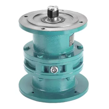
SC Transmission Cycloidal gearbox Cyclo Drivecyc lo gear box drive motor speed reducer gearboxes planetary CHINAMFG power industrial transmission best price manufacture Cycloidal gearbox
Product Description
Cyclo Drive are unsurpassed where drive technology is concerned. The Cyclo drive is superior to traditional gear mechanisms, since it only operates with rolling force and is not exposed to shear forces. By comparison with gears with contact loads, Cyclo drives are more resistant and can absorb extreme shock loads by means of uniform load distribution over the power transmitting components. Cyclo drives and Cyclo drive geared motors are characterized by their reliability, long service life and outstanding efficiency, even under difficult conditions.
Applications:Conveyor systems,Food and sugar industry,Mixers and agitators,Metalworking machines,Water treatment plants,Recycling plants,Poultry Processing Equipment,Sawmills and woodworking machines,Rolling mills,Construction machinery,Paper industry
Cycloidal Reducer
Power range:0.12-90KW
Transmission ration range:7-650000
Output torque(Kn.m):top to 30
Product Parameters
Company Profile
FAQ
Shipping
| Application: | Motor, Machinery, Agricultural Machinery |
|---|---|
| Gear Shape: | Bevel Gear |
| Step: | Single-Step |
| Type: | Worm Reducer |
| Output Torque: | Top to 30 Kn.M |
| Mount Position: | Horizontal/Vertical |
| Samples: |
US$ 50/Piece
1 Piece(Min.Order) | |
|---|
| Customization: |
Available
| Customized Request |
|---|
Suitability of Cycloidal Gearboxes for High-Torque Applications
Cycloidal gearboxes are well-suited for high-torque applications due to their unique design and mechanical advantages. Here’s why they are suitable:
- Multiple Engagement Points: Cycloidal gearboxes have multiple teeth in contact at any given moment, distributing the load over a larger area. This reduces wear and stress on individual teeth, making them capable of handling high torque.
- High Load-Carrying Capacity: The design of the cycloidal mechanism, with its large number of pins and rollers, provides high load-carrying capacity. This makes them capable of transmitting significant torque without failure.
- Tight Tolerances: The precision and tight tolerances in the construction of cycloidal gearboxes ensure smooth and efficient power transmission even under heavy loads.
- Compact Design: Cycloidal gearboxes achieve high torque in a relatively compact size. This is particularly advantageous in applications where space is limited.
- High Gear Ratio: Cycloidal gearboxes can achieve high gear ratios, allowing them to convert lower input speeds into higher output torque, which is essential in high-torque applications.
These factors make cycloidal gearboxes a reliable choice for various high-torque applications across industries such as heavy machinery, robotics, material handling, and more.
Maintenance Requirements for Cycloidal Gearboxes
Maintaining cycloidal gearboxes is essential to ensure their optimal performance and longevity. Here are some maintenance practices to consider:
- Lubrication: Regular lubrication is crucial to prevent wear and friction between moving parts. Use high-quality lubricants recommended by the gearbox manufacturer.
- Inspections: Regularly inspect the gearbox for signs of wear, damage, or oil leakage. Address any issues promptly to prevent further damage.
- Cleaning: Keep the gearbox clean and free from debris that could interfere with its operation. Cleanliness helps prevent contamination and wear.
- Torque Checks: Periodically check the tightness of fasteners and bolts to ensure they are properly secured. Loose fasteners can lead to misalignment and reduced performance.
- Seal Maintenance: Check and maintain seals to prevent oil leakage. Damaged seals should be replaced promptly to avoid lubricant loss.
- Temperature Monitoring: Monitor the operating temperature of the gearbox to ensure it remains within the recommended range. Excessive heat can lead to premature wear.
- Alignment: Ensure that the gearbox is properly aligned with other components to prevent misalignment-related issues.
- Regular Service: Follow the manufacturer’s recommended service intervals for more in-depth inspections and maintenance tasks.
Regular and proactive maintenance can extend the lifespan of cycloidal gearboxes, minimize downtime, and maintain their efficiency and performance over time.
Industries Benefiting from Cycloidal Gearboxes
Cycloidal gearboxes find applications in various industries where their unique characteristics are advantageous:
- Robotics and Automation: Cycloidal gearboxes are widely used in robotic systems for their compact design, high torque capacity, and precise motion control.
- Material Handling: Industries such as logistics and warehousing benefit from cycloidal gearboxes in conveyor systems due to their ability to handle heavy loads and provide smooth and accurate movement.
- Manufacturing: Equipment used in manufacturing processes, such as packaging machines and printing presses, often incorporate cycloidal gearboxes for their reliability and precise positioning.
- Aerospace: In aerospace applications, cycloidal gearboxes can be found in satellite systems, where their compactness and high torque-to-weight ratio are crucial.
- Medical Devices: Cycloidal gearboxes are used in medical equipment like robotic surgery systems for their precise movement capabilities and space-saving design.
- Defense: Military applications, such as remotely operated vehicles and surveillance equipment, benefit from cycloidal gearboxes’ ability to handle rugged conditions and provide precise control.
These industries leverage the advantages of cycloidal gearboxes to enhance the performance and efficiency of their systems.


editor by CX 2023-11-17
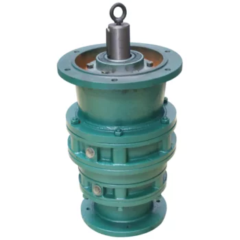
China Standard CZPT Xb Bwd/Xwd Transmission Gear Boxes Servo Motor CZPT Drive Pin Wheel Reducer Planetary Cyclo Cycloid Cycloidal Gearbox bevel gearbox
Product Description
CNC Machining Pins Zinc Plating
Product Description
1. Precision CNC machining parts strictly follow customer’s drawing,packing and quality requirement.
2. Tolerance: between+/-0.01mm;
3. The high-tech CMM inspector to ensure the quality;
4. Full-Experienced engineers and well professional trained workers;
5. Fast delivery time;
6. Professional advice for our customers;
Detailed Photos
Product Parameters
Our advantage of cnc machining:
| Business Type | Beyond the Manufacturer and strong organized ability in the industrial |
| Benefits | 1. Deeper industrial experience at CNC machining parts service for more than 10-years,our customer’s requirement is our 1st priority. 2. 2D or 3D files is available; 3. We trust the quality priority and we insist the good quality should be based on the customers’ satisfied; 4. Without any MOQ requirement; 5.Faster delivery time; 6. Customized size and specification /OEM available 7. Near ZheJiang Port |
The material
| Materials Accept |
Stainless Steel | SS201, SS303, SS304, SS316 etc. |
| Steel | Q235, 20#, 45#, | |
| Brass | C36000 ( C26800), C37700 ( HPb59), C38500( HPb58), C27200(CuZn37) , C28000(CuZn40) | |
| Iron | 1213, 12L14,1215 etc. | |
| Bronze | C51000, C52100, C54400, etc. | |
| Aluminum | Al6061, Al6063,AL7075,AL5052 etc | |
| Plastic | ABS,POM,PC(Poly-Carbonate),PC+GF,PA(nylon),PA+GF, PMMA(acrylic)PEEK,PEI etc) |
Packaging & Shipping
- We prefer DHL or TNT express or other air freight between 1kg-100kg.
- we prefer sea freight more than 100kg or more than 1CBM
- As per customized specifications.
Company Profile
About us
HangZhou CHINAMFG Technology Co.,Ltd is located in HangZhou City, ZheJiang Province, Which closed the ZheJiang .The Emitech Technology is mainly engaged in the CNC Machinery Industrial Service for 15 years. Our Parts are sold to Europe, America, Japan, South Korea and China in various kinds of industrial.At present, Our company has CNC Turning machines and CNC centers and equip with professional quality and testing instruments.We have full OEM Experience from worldwide, providing them with One-stop solutions for a broad range of applications.We look CHINAMFG to cooperating with you!
Our Advantages
1. Precision CNC machining parts strictly follow customer’s drawing,packing and quality requirement.
2. Tolerance: between+/-0.01mm;
3. The high-tech CMM inspector to ensure the quality;
4. Full-Experienced engineers and well professional trained workers;
5. Fast delivery time;
6. Professional advice for our customers;
After Sales Service
Customized Precision 5 Axis Cnc Milling Service Machining Metal Block Machined Anodized Aluminum Parts
We usually provide 12 Months repair service. If our duty, we will respond to send the new parts.
Our Service
| Our Processing | CNC center, CNC milling, CNC turning, drilling, grinding, bending, stamping, tapping, |
| Surface finish | Polishing, sandblasting,Zinc-plated, nickel-plated, chrome-plated, silver-plated, gold-plated, imitation gold-plated, |
| Tolerance | 0.05mm~0.1mm |
| QC System | 100% inspection before shipment |
| Drawing format | CAD / PDF/ DWG/ IGS/ STEP |
| Packaging | Plastic bag/Standard package / Carton or Pallet / As per customized specifications |
| Payment Terms | 30 -50%T/T in advance, 70-50% balance before delivery; Pay Pal or Western Union is acceptable. |
| Trade terms | EXW, FOB, CIF, As per the customer’s request |
| Shipment Terms |
1)We prefer DHL or TNT express or other air freight between 1kg-100kg. 2) we prefer sea freight more than 100kg or more than 1CBM |
| Note | The CNC machining parts are usually custom-made based on the customer’s drawings and samples. So we need the Down Payment |
| After-sales Service: | Repaire |
|---|---|
| Warranty: | Half a Year |
| Condition: | New |
| Certification: | CE, RoHS, GS, ISO9001 |
| Standard: | DIN, ASTM, GOST, GB, JIS, ANSI, BS |
| Customized: | Customized |
| Samples: |
US$ 10/Piece
1 Piece(Min.Order) | |
|---|
| Customization: |
Available
| Customized Request |
|---|
Distinguishing Features of Cycloidal Gearboxes
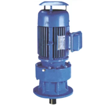
Cycloidal gearboxes, also known as cycloidal drives or cycloidal reducers, possess distinct characteristics that set them apart from other types of gearboxes:
- Principle of Operation: Cycloidal gearboxes utilize the principle of cycloidal motion, where input shaft movement is transformed into eccentric motion of the cycloidal disc. This unique mechanism results in smooth and consistent output motion.
- Compactness: Cycloidal gearboxes are renowned for their compact size and high torque density. The concentric design of the components contributes to their ability to transmit substantial torque in a relatively small package.
- Tooth Profile: Cycloidal gearboxes employ specialized cycloidal teeth, which involve both pinwheel and roller gears. This distinctive tooth profile contributes to the characteristic smooth and vibration-free operation.
- Reduction Mechanism: They often employ multi-lobed cam gears that interact with the pins on the cycloidal disc, resulting in multiple gear engagements per revolution and improved load distribution.
- Motion Control: Cycloidal gearboxes offer high positional accuracy and motion control due to the eccentric motion of the disc, making them suitable for robotics, automation, and precision applications.
- Backlash: They typically exhibit low backlash due to the nature of the engagement mechanism, making them advantageous for applications requiring precise and reversible motion.
- Applications: Cycloidal gearboxes are commonly used in various industries, including robotics, packaging, material handling, printing, and more, where their compactness, precision, and efficiency are valued.
These distinguishing features contribute to the unique capabilities and benefits of cycloidal gearboxes in specific applications.
Noise and Vibration Considerations in Cycloidal Gearboxes
Cycloidal gearboxes are generally known for their smooth and quiet operation. However, like any mechanical system, they can still exhibit some level of noise and vibration. Here are the key factors to consider:
- Gear Design: The unique rolling contact design of cycloidal gears contributes to their relatively low noise levels. The teeth engagement is gradual and continuous, reducing impact forces and noise.
- Lubrication: Proper lubrication is essential to minimize friction and noise. Using high-quality lubricants and maintaining proper lubrication levels can help reduce noise and vibration in cycloidal gearboxes.
- Precision Manufacturing: Precise manufacturing processes and tight tolerances can help minimize irregularities in gear meshing, which can contribute to noise and vibration.
- Load Distribution: Proper load distribution among multiple lobes in the cycloidal mechanism can help prevent localized stress concentrations that could lead to vibrations and noise.
- Bearing Quality: High-quality bearings can contribute to smooth operation and reduce vibrations that could be transmitted to the gearbox housing.
- Mounting and Installation: Proper mounting and alignment of the gearbox are important to ensure that it operates smoothly and without excessive vibrations.
While cycloidal gearboxes are designed to minimize noise and vibration, it’s important to consider the specific application, environmental conditions, and operating parameters. Regular maintenance, proper lubrication, and selecting the appropriate gearbox size and type can all contribute to reducing noise and vibration levels in cycloidal gearboxes.

Industries Benefiting from Cycloidal Gearboxes
Cycloidal gearboxes find applications in various industries where their unique characteristics are advantageous:
- Robotics and Automation: Cycloidal gearboxes are widely used in robotic systems for their compact design, high torque capacity, and precise motion control.
- Material Handling: Industries such as logistics and warehousing benefit from cycloidal gearboxes in conveyor systems due to their ability to handle heavy loads and provide smooth and accurate movement.
- Manufacturing: Equipment used in manufacturing processes, such as packaging machines and printing presses, often incorporate cycloidal gearboxes for their reliability and precise positioning.
- Aerospace: In aerospace applications, cycloidal gearboxes can be found in satellite systems, where their compactness and high torque-to-weight ratio are crucial.
- Medical Devices: Cycloidal gearboxes are used in medical equipment like robotic surgery systems for their precise movement capabilities and space-saving design.
- Defense: Military applications, such as remotely operated vehicles and surveillance equipment, benefit from cycloidal gearboxes’ ability to handle rugged conditions and provide precise control.
These industries leverage the advantages of cycloidal gearboxes to enhance the performance and efficiency of their systems.


editor by CX 2023-10-07
China high quality CZPT Xb Bwd/Xwd Transmission Gear Boxes Servo Motor CZPT Drive Pin Wheel Reducer Planetary Cyclo Cycloid Cycloidal Gearbox automatic gearbox
Product Description
SC Transmission Cycloidal gearbox Cyclo Drivecyc lo gear box drive motor speed reducer gearboxes planetary CZPT power industrial transmission best price manufacture Cycloidal gearbox
Product Description
Cyclo Drive are unsurpassed where drive technology is concerned. The Cyclo drive is superior to traditional gear mechanisms, since it only operates with rolling force and is not exposed to shear forces. By comparison with gears with contact loads, Cyclo drives are more resistant and can absorb extreme shock loads by means of uniform load distribution over the power transmitting components. Cyclo drives and Cyclo drive geared motors are characterized by their reliability, long service life and outstanding efficiency, even under difficult conditions.
Applications:Conveyor systems,Food and sugar industry,Mixers and agitators,Metalworking machines,Water treatment plants,Recycling plants,Poultry Processing Equipment,Sawmills and woodworking machines,Rolling mills,Construction machinery,Paper industry
Cycloidal Reducer
Power range:0.12-90KW
Transmission ration range:7-650000
Output torque(Kn.m):top to 30
Product Parameters
Company Profile
FAQ
Shipping
| Application: | Motor, Machinery, Agricultural Machinery |
|---|---|
| Gear Shape: | Bevel Gear |
| Step: | Single-Step |
| Type: | Worm Reducer |
| Motor: | Can Be Matched with The Motor |
| Ratio: | 7-650000 |
| Samples: |
US$ 50/Piece
1 Piece(Min.Order) | |
|---|
| Customization: |
Available
| Customized Request |
|---|

How Does a Cycloidal Gearbox Work?
A cycloidal gearbox
Suitability of Cycloidal Gearboxes for High-Torque Applications
Cycloidal gearboxes are well-suited for high-torque applications due to their unique design and mechanical advantages. Here’s why they are suitable:
- Multiple Engagement Points: Cycloidal gearboxes have multiple teeth in contact at any given moment, distributing the load over a larger area. This reduces wear and stress on individual teeth, making them capable of handling high torque.
- High Load-Carrying Capacity: The design of the cycloidal mechanism, with its large number of pins and rollers, provides high load-carrying capacity. This makes them capable of transmitting significant torque without failure.
- Tight Tolerances: The precision and tight tolerances in the construction of cycloidal gearboxes ensure smooth and efficient power transmission even under heavy loads.
- Compact Design: Cycloidal gearboxes achieve high torque in a relatively compact size. This is particularly advantageous in applications where space is limited.
- High Gear Ratio: Cycloidal gearboxes can achieve high gear ratios, allowing them to convert lower input speeds into higher output torque, which is essential in high-torque applications.
These factors make cycloidal gearboxes a reliable choice for various high-torque applications across industries such as heavy machinery, robotics, material handling, and more.
operates on the principle of cycloidal motion to transmit rotational power. It consists of a set of components that work together to achieve smooth and efficient motion transmission:
- High-Speed Input Shaft: The gearbox is connected to a high-speed input shaft, typically driven by an electric motor or another power source.
- Cycloidal Pins or Rollers: Surrounding the input shaft are a series of cycloidal pins or rollers arranged in a circular pattern. These pins interact with the lobed profiles of the outer stationary ring.
- Outer Stationary Ring: The outer ring remains stationary and contains lobed profiles. The lobes are designed in a way that allows them to engage with the cycloidal pins as they rotate.
- Motion Transmission: As the input shaft rotates, it causes the cycloidal pins to move along the circular path. The interaction between the cycloidal pins and the lobed profiles of the outer ring results in a unique motion known as epicycloidal or hypocycloidal motion.
This motion generates torque that is transferred from the input shaft to the output shaft of the gearbox. The main advantage of a cycloidal gearbox is its ability to provide high torque output in a compact design. The multiple points of contact between the pins and the lobes distribute the load, enhancing the gearbox’s load-carrying capacity.
Cycloidal gearboxes are known for their smooth and controlled motion, making them suitable for applications requiring precise positioning and high torque capa
Noise and Vibration Considerations in Cycloidal Gearboxes
Cycloidal gearboxes are generally known for their smooth and quiet operation. However, like any mechanical system, they can still exhibit some level of noise and vibration. Here are the key factors to consider:
- Gear Design: The unique rolling contact design of cycloidal gears contributes to their relatively low noise levels. The teeth engagement is gradual and continuous, reducing impact forces and noise.
- Lubrication: Proper lubrication is essential to minimize friction and noise. Using high-quality lubricants and maintaining proper lubrication levels can help reduce noise and vibration in cycloidal gearboxes.
- Precision Manufacturing: Precise manufacturing processes and tight tolerances can help minimize irregularities in gear meshing, which can contribute to noise and vibration.
- Load Distribution: Proper load distribution among multiple lobes in the cycloidal mechanism can help prevent localized stress concentrations that could lead to vibrations and noise.
- Bearing Quality: High-quality bearings can contribute to smooth operation and reduce vibrations that could be transmitted to the gearbox housing.
- Mounting and Installation: Proper mounting and alignment of the gearbox are important to ensure that it operates smoothly and without excessive vibrations.
While cycloidal gearboxes are designed to minimize noise and vibration, it’s important to consider the specific application, environmental conditions, and operating parameters. Regular maintenance, proper lubrication, and selecting the appropriate gearbox size and type can all contribute to reducing noise and vibration levels in cycloidal gearboxes.
bilities, such as robotics, automation, and industrial machinery.


editor by CX 2023-08-22
China High Precision Low Backlash Helical Gear Planetary Speed Reducer Gearbox for Servo Motor Manipulator Mechanical Arm with Great quality
Merchandise Description
TaiBang Motor Industry Group Co., Ltd.
The main merchandise is induction motor, reversible motor, DC brush equipment motor, DC brushless gear motor, CH/CV massive equipment motors, Planetary equipment motor ,Worm gear motor etc, which utilized commonly in different fields of manufacturing pipelining, transportation, foods, medication, printing, fabric, packing, place of work, equipment, amusement and many others, and is the preferred and matched merchandise for automated device.
Product Instruction
| GB | 090 | 571 | P2 |
| Reducer Series Code | Exterior Diameter | Reduction Ratio | Reducer Backlash |
| GB:Large Precision Sq. Flange Output
GBR:Substantial Precision Proper Angle Sq. Flange Output GE:High Precision Spherical Flange Output GER:Large Precision Correct Spherical Flange Output |
050:ø50mm 070:ø70mm 090:ø90mm one hundred twenty:ø120mm a hundred and fifty five:ø155mm 205:ø205mm 235:ø235mm 042:42x42mm 060:60x60mm 090:90x90mm a hundred and fifteen:115x115mm 142:142x142mm a hundred and eighty:180x180mm 220:220x220mm |
571 means 1:ten | P0:Large Precision Backlash
P1:Precison Backlash P2:Common Backlash |
Principal Technological Functionality
| Product | Number of stage | Reduction Ratio | GB042 | GB060 | GB060A | GB090 | GB090A | GB115 | GB142 | GB180 | GB220 |
| Rotary Inertia | 1 | 3 | .03 | .sixteen | .61 | three.twenty five | 9.21 | 28.98 | sixty nine.61 | ||
| 4 | .03 | .14 | .48 | 2.seventy four | 7.fifty four | 23.sixty seven | fifty four.37 | ||||
| 5 | .03 | .13 | .47 | 2.seventy one | seven.forty two | 23.29 | 53.27 | ||||
| six | .03 | .13 | .forty five | 2.sixty five | 7.twenty five | 22.seventy five | fifty one.72 | ||||
| 7 | .03 | .thirteen | .45 | two.62 | seven.fourteen | 22.48 | fifty.ninety seven | ||||
| eight | .03 | .13 | .44 | 2.fifty eight | 7.07 | 22.59 | 50.84 | ||||
| nine | .03 | .thirteen | .forty four | 2.57 | 7.04 | 22.fifty three | fifty.sixty three | ||||
| 10 | .03 | .13 | .44 | 2.fifty seven | seven.03 | 22.fifty one | fifty.56 | ||||
| 2 | 15 | .03 | .03 | .13 | .13 | .47 | .47 | 2.seventy one | 7.forty two | 23.29 | |
| 20 | .03 | .03 | .thirteen | .13 | .47 | .47 | two.71 | seven.42 | 23.29 | ||
| twenty five | .03 | .03 | .13 | .thirteen | .47 | .47 | two.71 | 7.forty two | 23.29 | ||
| 30 | .03 | .03 | .thirteen | .thirteen | .forty seven | .47 | two.seventy one | seven.forty two | 23.29 | ||
| 35 | .03 | .03 | .13 | .13 | .47 | .47 | two.seventy one | 7.42 | 23.29 | ||
| 40 | .03 | .03 | .thirteen | .13 | .forty seven | .47 | two.seventy one | 7.42 | 23.29 | ||
| forty five | .03 | .03 | .13 | .thirteen | .47 | .forty seven | 2.71 | seven.forty two | 23.29 | ||
| 50 | .03 | .03 | .thirteen | .13 | .forty four | .44 | two.57 | 7.03 | 22.fifty one | ||
| sixty | .03 | .03 | .13 | .13 | .forty four | .44 | 2.57 | seven.03 | 22.51 | ||
| 70 | .03 | .03 | .thirteen | .13 | .44 | .forty four | two.57 | 7.03 | 22.fifty one | ||
| 80 | .03 | .03 | .13 | .13 | .44 | .44 | 2.57 | 7.03 | 22.51 | ||
| 90 | .03 | .03 | .thirteen | .thirteen | .44 | .44 | 2.57 | 7.03 | 22.51 | ||
| a hundred | .03 | .03 | .13 | .13 | .forty four | .forty four | two.57 | 7.03 | 22.fifty one |
| Item | Amount of phase | GB042 | GB060 | GB060A | GB90 | GB090A | GB115 | GB142 | GB180 | GB220 | |
| Backlash(arcmin) | High Precision P0 | 1 | ≤1 | ≤1 | ≤1 | ≤1 | ≤1 | ≤1 | |||
| two | ≤3 | ≤3 | ≤3 | ≤3 | |||||||
| Precision P1 | 1 | ≤3 | ≤3 | ≤3 | ≤3 | ≤3 | ≤3 | ≤3 | ≤3 | ≤3 | |
| 2 | ≤5 | ≤5 | ≤5 | ≤5 | ≤5 | ≤5 | ≤5 | ≤5 | ≤5 | ||
| Standard P2 | 1 | ≤5 | ≤5 | ≤5 | ≤5 | ≤5 | ≤5 | ≤5 | ≤5 | ≤5 | |
| two | ≤7 | ≤7 | ≤7 | ≤7 | ≤7 | ≤7 | ≤7 | ≤7 | ≤7 | ||
| Torsional Rigidity(N.M/arcmin) | 1 | three | seven | seven | fourteen | 14 | twenty five | fifty | 145 | 225 | |
| two | three | 7 | 7 | 14 | 14 | 25 | 50 | 145 | 225 | ||
| Noise(dB) | 1,2 | ≤56 | ≤58 | ≤58 | ≤60 | ≤60 | ≤63 | ≤65 | ≤67 | ≤70 | |
| Rated enter speed(rpm) | one,two | 5000 | 5000 | 5000 | 4000 | 4000 | 4000 | 3000 | 3000 | 2000 | |
| Max input pace(rpm) | 1,2 | 10000 | ten thousand | ten thousand | 8000 | 8000 | 8000 | 6000 | 6000 | 4000 | |
Noise examination regular:Length 1m,no load.Measured with an enter speed 3000rpm
|
US $50 / Piece | |
1 Piece (Min. Order) |
###
| Application: | Machinery, Agricultural Machinery, Automatic Machinery |
|---|---|
| Function: | Distribution Power, Change Drive Torque, Change Drive Direction, Speed Reduction |
| Layout: | Cycloidal |
| Hardness: | Hardened Tooth Surface |
| Installation: | Vertical Type |
| Step: | Double-Step |
###
| Samples: |
US$ 50/Piece
1 Piece(Min.Order) |
|---|
###
| Customization: |
Available
|
|---|
###
| GB | 090 | 010 | P2 |
| Reducer Series Code | External Diameter | Reduction Ratio | Reducer Backlash |
| GB:High Precision Square Flange Output
GBR:High Precision Right Angle Square Flange Output GE:High Precision Round Flange Output GER:High Precision Right Round Flange Output |
050:ø50mm 070:ø70mm 090:ø90mm 120:ø120mm 155:ø155mm 205:ø205mm 235:ø235mm 042:42x42mm 060:60x60mm 090:90x90mm 115:115x115mm 142:142x142mm 180:180x180mm 220:220x220mm |
010 means 1:10 | P0:High Precision Backlash
P1:Precison Backlash P2:Standard Backlash |
###
| Item | Number of stage | Reduction Ratio | GB042 | GB060 | GB060A | GB090 | GB090A | GB115 | GB142 | GB180 | GB220 |
| Rotary Inertia | 1 | 3 | 0.03 | 0.16 | 0.61 | 3.25 | 9.21 | 28.98 | 69.61 | ||
| 4 | 0.03 | 0.14 | 0.48 | 2.74 | 7.54 | 23.67 | 54.37 | ||||
| 5 | 0.03 | 0.13 | 0.47 | 2.71 | 7.42 | 23.29 | 53.27 | ||||
| 6 | 0.03 | 0.13 | 0.45 | 2.65 | 7.25 | 22.75 | 51.72 | ||||
| 7 | 0.03 | 0.13 | 0.45 | 2.62 | 7.14 | 22.48 | 50.97 | ||||
| 8 | 0.03 | 0.13 | 0.44 | 2.58 | 7.07 | 22.59 | 50.84 | ||||
| 9 | 0.03 | 0.13 | 0.44 | 2.57 | 7.04 | 22.53 | 50.63 | ||||
| 10 | 0.03 | 0.13 | 0.44 | 2.57 | 7.03 | 22.51 | 50.56 | ||||
| 2 | 15 | 0.03 | 0.03 | 0.13 | 0.13 | 0.47 | 0.47 | 2.71 | 7.42 | 23.29 | |
| 20 | 0.03 | 0.03 | 0.13 | 0.13 | 0.47 | 0.47 | 2.71 | 7.42 | 23.29 | ||
| 25 | 0.03 | 0.03 | 0.13 | 0.13 | 0.47 | 0.47 | 2.71 | 7.42 | 23.29 | ||
| 30 | 0.03 | 0.03 | 0.13 | 0.13 | 0.47 | 0.47 | 2.71 | 7.42 | 23.29 | ||
| 35 | 0.03 | 0.03 | 0.13 | 0.13 | 0.47 | 0.47 | 2.71 | 7.42 | 23.29 | ||
| 40 | 0.03 | 0.03 | 0.13 | 0.13 | 0.47 | 0.47 | 2.71 | 7.42 | 23.29 | ||
| 45 | 0.03 | 0.03 | 0.13 | 0.13 | 0.47 | 0.47 | 2.71 | 7.42 | 23.29 | ||
| 50 | 0.03 | 0.03 | 0.13 | 0.13 | 0.44 | 0.44 | 2.57 | 7.03 | 22.51 | ||
| 60 | 0.03 | 0.03 | 0.13 | 0.13 | 0.44 | 0.44 | 2.57 | 7.03 | 22.51 | ||
| 70 | 0.03 | 0.03 | 0.13 | 0.13 | 0.44 | 0.44 | 2.57 | 7.03 | 22.51 | ||
| 80 | 0.03 | 0.03 | 0.13 | 0.13 | 0.44 | 0.44 | 2.57 | 7.03 | 22.51 | ||
| 90 | 0.03 | 0.03 | 0.13 | 0.13 | 0.44 | 0.44 | 2.57 | 7.03 | 22.51 | ||
| 100 | 0.03 | 0.03 | 0.13 | 0.13 | 0.44 | 0.44 | 2.57 | 7.03 | 22.51 |
###
| Item | Number of stage | GB042 | GB060 | GB060A | GB90 | GB090A | GB115 | GB142 | GB180 | GB220 | |
| Backlash(arcmin) | High Precision P0 | 1 | ≤1 | ≤1 | ≤1 | ≤1 | ≤1 | ≤1 | |||
| 2 | ≤3 | ≤3 | ≤3 | ≤3 | |||||||
| Precision P1 | 1 | ≤3 | ≤3 | ≤3 | ≤3 | ≤3 | ≤3 | ≤3 | ≤3 | ≤3 | |
| 2 | ≤5 | ≤5 | ≤5 | ≤5 | ≤5 | ≤5 | ≤5 | ≤5 | ≤5 | ||
| Standard P2 | 1 | ≤5 | ≤5 | ≤5 | ≤5 | ≤5 | ≤5 | ≤5 | ≤5 | ≤5 | |
| 2 | ≤7 | ≤7 | ≤7 | ≤7 | ≤7 | ≤7 | ≤7 | ≤7 | ≤7 | ||
| Torsional Rigidity(N.M/arcmin) | 1 | 3 | 7 | 7 | 14 | 14 | 25 | 50 | 145 | 225 | |
| 2 | 3 | 7 | 7 | 14 | 14 | 25 | 50 | 145 | 225 | ||
| Noise(dB) | 1,2 | ≤56 | ≤58 | ≤58 | ≤60 | ≤60 | ≤63 | ≤65 | ≤67 | ≤70 | |
| Rated input speed(rpm) | 1,2 | 5000 | 5000 | 5000 | 4000 | 4000 | 4000 | 3000 | 3000 | 2000 | |
| Max input speed(rpm) | 1,2 | 10000 | 10000 | 10000 | 8000 | 8000 | 8000 | 6000 | 6000 | 4000 | |
|
US $50 / Piece | |
1 Piece (Min. Order) |
###
| Application: | Machinery, Agricultural Machinery, Automatic Machinery |
|---|---|
| Function: | Distribution Power, Change Drive Torque, Change Drive Direction, Speed Reduction |
| Layout: | Cycloidal |
| Hardness: | Hardened Tooth Surface |
| Installation: | Vertical Type |
| Step: | Double-Step |
###
| Samples: |
US$ 50/Piece
1 Piece(Min.Order) |
|---|
###
| Customization: |
Available
|
|---|
###
| GB | 090 | 010 | P2 |
| Reducer Series Code | External Diameter | Reduction Ratio | Reducer Backlash |
| GB:High Precision Square Flange Output
GBR:High Precision Right Angle Square Flange Output GE:High Precision Round Flange Output GER:High Precision Right Round Flange Output |
050:ø50mm 070:ø70mm 090:ø90mm 120:ø120mm 155:ø155mm 205:ø205mm 235:ø235mm 042:42x42mm 060:60x60mm 090:90x90mm 115:115x115mm 142:142x142mm 180:180x180mm 220:220x220mm |
010 means 1:10 | P0:High Precision Backlash
P1:Precison Backlash P2:Standard Backlash |
###
| Item | Number of stage | Reduction Ratio | GB042 | GB060 | GB060A | GB090 | GB090A | GB115 | GB142 | GB180 | GB220 |
| Rotary Inertia | 1 | 3 | 0.03 | 0.16 | 0.61 | 3.25 | 9.21 | 28.98 | 69.61 | ||
| 4 | 0.03 | 0.14 | 0.48 | 2.74 | 7.54 | 23.67 | 54.37 | ||||
| 5 | 0.03 | 0.13 | 0.47 | 2.71 | 7.42 | 23.29 | 53.27 | ||||
| 6 | 0.03 | 0.13 | 0.45 | 2.65 | 7.25 | 22.75 | 51.72 | ||||
| 7 | 0.03 | 0.13 | 0.45 | 2.62 | 7.14 | 22.48 | 50.97 | ||||
| 8 | 0.03 | 0.13 | 0.44 | 2.58 | 7.07 | 22.59 | 50.84 | ||||
| 9 | 0.03 | 0.13 | 0.44 | 2.57 | 7.04 | 22.53 | 50.63 | ||||
| 10 | 0.03 | 0.13 | 0.44 | 2.57 | 7.03 | 22.51 | 50.56 | ||||
| 2 | 15 | 0.03 | 0.03 | 0.13 | 0.13 | 0.47 | 0.47 | 2.71 | 7.42 | 23.29 | |
| 20 | 0.03 | 0.03 | 0.13 | 0.13 | 0.47 | 0.47 | 2.71 | 7.42 | 23.29 | ||
| 25 | 0.03 | 0.03 | 0.13 | 0.13 | 0.47 | 0.47 | 2.71 | 7.42 | 23.29 | ||
| 30 | 0.03 | 0.03 | 0.13 | 0.13 | 0.47 | 0.47 | 2.71 | 7.42 | 23.29 | ||
| 35 | 0.03 | 0.03 | 0.13 | 0.13 | 0.47 | 0.47 | 2.71 | 7.42 | 23.29 | ||
| 40 | 0.03 | 0.03 | 0.13 | 0.13 | 0.47 | 0.47 | 2.71 | 7.42 | 23.29 | ||
| 45 | 0.03 | 0.03 | 0.13 | 0.13 | 0.47 | 0.47 | 2.71 | 7.42 | 23.29 | ||
| 50 | 0.03 | 0.03 | 0.13 | 0.13 | 0.44 | 0.44 | 2.57 | 7.03 | 22.51 | ||
| 60 | 0.03 | 0.03 | 0.13 | 0.13 | 0.44 | 0.44 | 2.57 | 7.03 | 22.51 | ||
| 70 | 0.03 | 0.03 | 0.13 | 0.13 | 0.44 | 0.44 | 2.57 | 7.03 | 22.51 | ||
| 80 | 0.03 | 0.03 | 0.13 | 0.13 | 0.44 | 0.44 | 2.57 | 7.03 | 22.51 | ||
| 90 | 0.03 | 0.03 | 0.13 | 0.13 | 0.44 | 0.44 | 2.57 | 7.03 | 22.51 | ||
| 100 | 0.03 | 0.03 | 0.13 | 0.13 | 0.44 | 0.44 | 2.57 | 7.03 | 22.51 |
###
| Item | Number of stage | GB042 | GB060 | GB060A | GB90 | GB090A | GB115 | GB142 | GB180 | GB220 | |
| Backlash(arcmin) | High Precision P0 | 1 | ≤1 | ≤1 | ≤1 | ≤1 | ≤1 | ≤1 | |||
| 2 | ≤3 | ≤3 | ≤3 | ≤3 | |||||||
| Precision P1 | 1 | ≤3 | ≤3 | ≤3 | ≤3 | ≤3 | ≤3 | ≤3 | ≤3 | ≤3 | |
| 2 | ≤5 | ≤5 | ≤5 | ≤5 | ≤5 | ≤5 | ≤5 | ≤5 | ≤5 | ||
| Standard P2 | 1 | ≤5 | ≤5 | ≤5 | ≤5 | ≤5 | ≤5 | ≤5 | ≤5 | ≤5 | |
| 2 | ≤7 | ≤7 | ≤7 | ≤7 | ≤7 | ≤7 | ≤7 | ≤7 | ≤7 | ||
| Torsional Rigidity(N.M/arcmin) | 1 | 3 | 7 | 7 | 14 | 14 | 25 | 50 | 145 | 225 | |
| 2 | 3 | 7 | 7 | 14 | 14 | 25 | 50 | 145 | 225 | ||
| Noise(dB) | 1,2 | ≤56 | ≤58 | ≤58 | ≤60 | ≤60 | ≤63 | ≤65 | ≤67 | ≤70 | |
| Rated input speed(rpm) | 1,2 | 5000 | 5000 | 5000 | 4000 | 4000 | 4000 | 3000 | 3000 | 2000 | |
| Max input speed(rpm) | 1,2 | 10000 | 10000 | 10000 | 8000 | 8000 | 8000 | 6000 | 6000 | 4000 | |
How to Use a Cyclone Gearbox
Often, a cycloidal gearbox is used in order to achieve a torque transfer from a motor or pump. This type of gearbox is often a common choice as it has a number of advantages over a regular gearbox. Its main advantage is that it is easy to make, which means that it can be incorporated into a variety of applications. However, if you want to use a cycloidal gearbox, there are a few things that you need to know. These include the operation principle, the structure and the dynamic and inertial effects that come with it.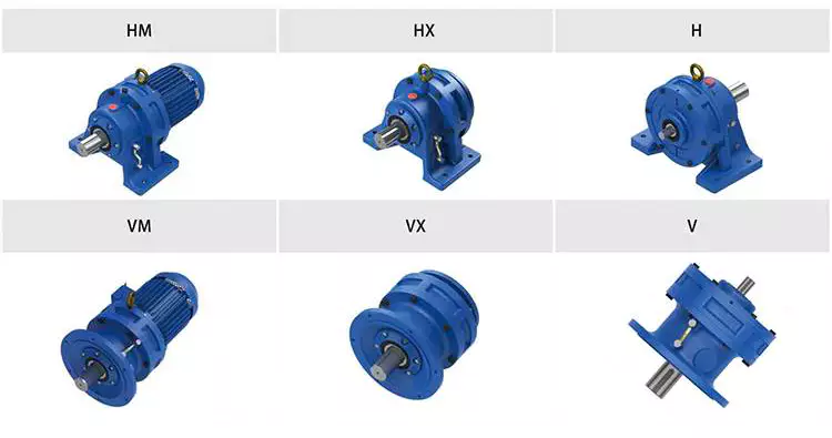
Dynamic and inertial effects
Several studies have been carried out on the static and dynamic properties of cycloidal gears. The study of these effects is beneficial in assisting optimal design of cycloidal speed reducers.
In this paper, the dynamic and inertial effects of a two-stage cycloidal speed reducer have been investigated using the CZPT program package. Moreover, a new model for cycloidal reducers based on non-linear contact dynamics has been developed. The new model aims to predict several operational conditions.
The normal excitation contact force for the cycloid discs of the first and second stage is very similar. However, the total deformation at the contact point is different. This effect is mainly due to the system’s own oscillations. The cycloid discs of the second stage turn around the ring gear roller with a 180deg angle. This angle is a significant contributor to the torque loads. The total excitation force on the cycloid discs of first and second stage is 1848 N and 2068.7 N, respectively.
In order to analyze the contact stress, different gear profiles were investigated. The mesh density was considered as an important design criterion. It was found that a bigger hole reduces the material content of the cycloidal disc and results in more stresses.
Moreover, it is possible to reduce the contact forces in a more efficient manner by changing the geometric parameters. This can be done by mesh refinement along the disc width. The cycloidal disc has the greatest influence on the output results.
The efficiency of a cycloidal drive increases with the increase in load. The efficiency of a cycloidal reducer also depends on the eccentricity of the input shaft and the cycloidal plate. The efficiency curve for small loads is linear. However, for the larger loads, the efficiency curve becomes more non-linear. This is because the stiffness of the cycloid reducer increases as the load increases.
Structure
Despite the fact that it looks like a complicated engineering puzzle, the construction of a cycloidal gearbox is actually quite simple. The key elements are the base, the load plate and the thrust bearing. All these elements work together to create a stable, compact gearbox.
The base is a circular section with several cylindrical pins around its outer edge. The pins are fixed on a fixed ring that holds them in a circular path. The ring serves as a reference circle. The circle’s size is approximately 5mm in diameter.
The load plate is a series of threaded screw holes. These are arranged 15mm away from the center. These are used to anchor external structures. The load plate must be rotated around the X and Y axis.
The thrust bearing is placed on top of the load plate. The bearing is made of an internal diameter of 35mm and an external diameter of 52mm. It is used to allow rotation around the Z axis.
The cycloidal disc is the centerpiece of the cycloidal gearbox. The disc has holes for the pins that drive the output shaft. The holes are larger than those used in output roller pins. The disc also has a reduced eccentricity.
The pins are attached to the cycloidal disc by rolling pins. The pins are made of a material that provides mechanical support for the drive during high-torque situations. The pins have a 9mm external diameter. The disc has a number of lobes and is rotated by one lobe per shaft revolution.
The cycloidal gearbox also has a top cover that helps keep the components together. The cover has a pocket for tools. The top cover also has threads that screw into the casing.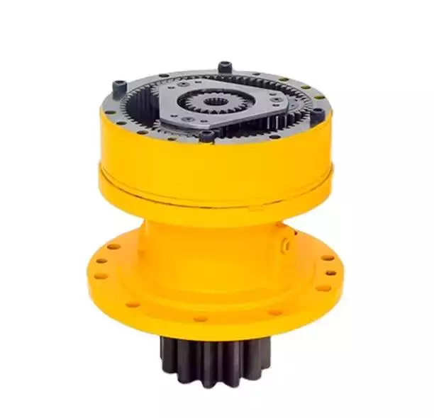
Operation principle
Among many types of gear transmissions, cycloidal gearboxes are used in heavy machinery and multi-axis robots. They are highly effective, compact and capable of high ratios. In addition, they have an overload capability.
Cycloid disks are driven by eccentric shafts that rotate around fixed ring pins. Roller pins of the pin disc engage with holes in the cycloidal disc. These roller pins drive the pin disc and the pin disc transfers the motion to the output shaft.
Unlike conventional gear drives, cycloidal drives have low backlash and high torsional stiffness. They are ideally suited to heavy loads and all drive technologies. The lower mass and compact design of the cycloidal disk also contributes to its high efficiency and positioning accuracy.
The cycloidal disc plays a central role in the gearbox kinematics. It rotates around a fixed ring in a circle. When the disc is pushed against the ring gear, the pins engage with the disc and the roller pins rotate around the pins. This rotating motion generates vibration, which travels through the driven shafts.
Cycloid discs are typically designed with a short cycloid, so that the eccentricity is minimized. This reduces unbalance forces at high speeds. Ideally, the number of lobes on the cycloid is smaller than the number of surrounding pins. This reduces the amount of Hertzian contact stress.
Unlike planetary gears, cycloidal gears have high accuracy and are capable of withstanding shock loads. They also experience low friction and less wear on tooth flanks. They also have higher efficiency and load capacity.
Cycloid gears are generally more difficult to manufacture than involute gears. Cycloid gears are not suitable for stacking gear stages. They require extreme accuracy for manufacturing. However, their smaller size and low backlash, high torsional stiffness, and low vibration make them ideal for use in heavy machines.
Involute gear tooth profile
Almost all gears are manufactured with an involute gear tooth profile. Cycloid gears are also produced with this profile. Compared with involute gears, cycloid gears are stronger and can transmit more power. However, they can also be more difficult to manufacture. This makes them costlier.
The involute gear tooth profile is a smooth curve. It is derived from the involute curve of a circle. A tangent to the base circle is the normal at any point of an involute.
This curve has properties that allow the involute gear teeth to transfer motion in perpendicular direction. It is also the path traced by the end of the string unwrapping from a cylinder.
An involute profile has the advantage of being easy to manufacture. It also allows for smooth meshing despite misalignment of the centre distance. This profile is also preferred over a cycloid tooth profile, but it is not the best in every regard.
Cycloid gear teeth are also made of two curves. Unlike involute teeth, cycloid gear teeth have a consistent radius. Cycloid gears are less likely to produce noise. But they are also more expensive to manufacture.
Involute teeth are easier to manufacture because they have only one curve. Cycloid gears can also be made with a rack type cutter. This makes them cheaper to manufacture. However, they require an expert design. They can also be manufactured with a gear shaper that includes a pinion cutter.
The tooth profiles that satisfy the law of gear-tooth action are sometimes called conjugate profiles. The involute profile is the most common of these. It allows for constant torque transmission.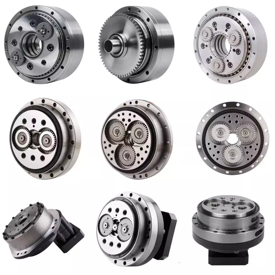
Backlash
Typically, cycloidal drives provide a high ratio of transmission with no backlash. This is because the cycloid disc is driven by an eccentric shaft. During rotation, the cycloid disc rotates around a fixed ring. This ring also rotates independently of the center of gravity.
The cycloid disc is typically shortened to reduce the eccentricity. This helps to minimize the unbalance forces that may occur at high speeds. The cycloid also offers a larger gear ratio than traditional gears. This provides a better positional accuracy.
Cycloid drives also have a high torsional stiffness. This provides greater torsional resilience and shock load capabilities. This is important for a number of reasons, such as in heavy-duty applications.
Cycloid drives also have lower mass. These benefits make them ideally suited for all drive technologies. The design also allows for higher torsional stiffness and service life. These drives also have a much smaller profile.
Cycloid drives are also used to reduce speed. Because of the high torsional stiffness of the cycloid, they also have high positioning accuracy.
Cycloid drives are well-suited to a variety of applications, including electric motors, generators, and pump motors. They are also highly resistant to shock loads, which is important in a variety of applications. This design is ideal for applications that require a large transmission ratio in a compact design.
Cycloid drives also have the advantage of minimizing the clearance between the mating components. This helps to eliminate interference and ensure a positive fit. This is particularly important in gearboxes. It also allows for the use of a load cell and potentiometer to determine the backlash of the gearbox.

editor by czh 2022-12-26
China Servo Motor fit Reducer Factory Price Cycloidal Transmit Planetary Gearbox for Sale sequential gearbox
Model Number: PF115
Gearing Arrangement: Planetary
Output Torque: 9-1000N.m
Rated Power: 200W-5000W
Input Speed: 200-3000rpm
Output Speed: 3.9-1000rpm
Ratio: 3~512
Material: Aluminum alloy
Average lifetime: 20000h
Weight: 0.9kg-10kg
match with motor: servor motor
Warranty: 1 year
Packaging Details: Safety Packing Method: 1.Plastic bags with Chemical Desiccant. 2.Individual Carton packaging. 3.Wooden Box outside.
Port: HangZhou/ZheJiang Port
Specification
| Type: | Planetary gearbox |
| Model: | 60.80.90.115.120.142.160 |
| Ratio: | 1-stage: 3.4.5.7.8.10 2-stage: 9.10.12.15.16.20.25.30.32.35.40.50.64.70.100 3-stage: 60.80.100.120.160.200.256.320.512 |
| Color: | Black/Silver or on customer request |
| Housing | Aluminum alloy |
| Packing | Carton/Wooden case |
| Warranty: | 1 Year |
| Usages: | Industrial Machine: Food Stuff, Ceramics ,CHEMICAL, Packing ,Dyeing ,Wooding working ,Glass |
Packaging & Shipping
Our Services
(1) With excellent quality
(2) Reasonable price(3) Promise to delivery on time(4) Large output torque(5) Safe, reliable, economical and durable(6) Stable transmission, quiet operation(7) High heat-radiating efficiency, high carrying ability(8) Certificate of quality: ISO9001:2008(9) Every product must be tested before sending(10)Made of high-quality aluminum alloy, light weight and non-rusting(11)Large output torque.(12) Smooth running and low noise.(13) High radiating efficiency.(14) Good-looking appearance, durable service life and small volume.(15) Suitable for Omni bearing installation.
Company Information
HangZhou Wanxing Reducer Co.,Ltd is specialized in R&D,manufacture and sales of transmissions. By taking the aim of “quality first and credit first”, we always strive for survival on the basis of quality and credit and strive for development on the basis of technology since our company was built as well as is the first to pass ISO9001:2000 International Quality System Certificate.
FAQ
1. Q: What’s type of your company.
A: We are manufacturer.
2. Q: what should I provide when I choose gearbox/speed reducer?
A: 1) load condition
2) speed of rotation or speed ratio(combination with combine speed reducer can get extra low out putting rotational speed)
3) work circumstance(temperature, humidty,corrosion etc.)
4) space of installation
3. Q: How long dose it take to finish my order?
A: It depends on your quantity. Generally 25days for 1 20GP, 35days for 1 40HQ.
4. Q: How can i know the process of my order?
A: Detailed picture of the production process will be sent to you to confirm before shipping.
Consummation QC system makes it possible to offer you reliable quality
Any query, feel free to contact me at any time.
WhatsApp: 13567338823
Wechat No.: g1571715719
The Different Types of Gearboxes
There are many different types of gearboxes. Some brands have more than one type. In this article, we’ll discuss the planetary gearbox, the worm reduction gearbox, the shaft mounted gearbox, and the one speed gearbox. This article will also help you determine which type of gearbox is best for your vehicle. And don’t worry if you don’t know the terminology yet. We’ll explain each type in detail so that you know what you’re getting yourself into.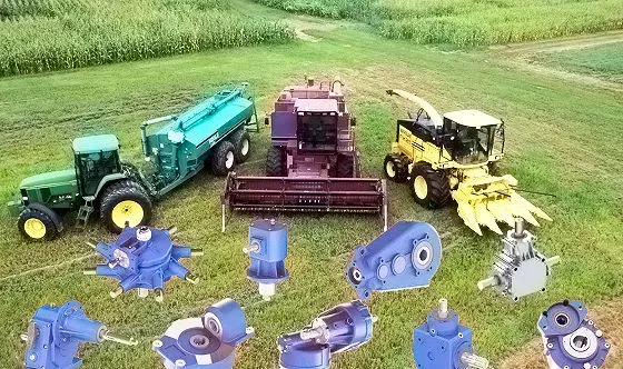
Planetary gearbox
Planetary gears have many advantages. The multiple gears in a planetary gearbox mesh simultaneously during operation. As such, they provide high efficiency and transmit high transmittable torque. These gears are widely used in various industries and are resistant to high shock loads and demanding conditions. CZPT is one of the companies that offer planetary gearboxes. Its products do not require special tools for assembly, and its scalable design minimizes safety stock.
Among the numerous benefits of planetary gearing is its compactness and lightweight. As such, it is suitable for wide applications with space and weight constraints. However, to truly appreciate its benefits, it is necessary to understand its mechanisms. Here are some of the most common details about planetary gearing:
The planetary gearbox has two mounted gears: an input shaft and an output shaft. Each gear has multiple teeth that are attached to a carrier and rotate with the input shaft. The carrier is connected to the output shaft. A planetary gear is mounted on both gears via a carrier. The carrier rotates in order to drive the planetary gear. The sun gear is often the input gear. The other gear is called the outer gear.
Planetary gearboxes are highly customizable. The size, mounting, and housing options vary, as do the reduction ratios and input speeds. Different types can be manufactured for different applications and include options such as electrical or mechanical preload. The final design of a planetary gearbox can be highly customized, based on the specifications of the application. By combining engineering excellence and ongoing innovation, planetary gearboxes provide years of trouble-free operation.
A planetary gearbox can be either an electric motor or a manual one. The latter has more features than the former, and can be used in applications where space is an issue. The primary features of a planetary gearbox include its backlash, torque, and ratio. Secondary features include noise, corrosion resistance, and construction. A planetary gearbox is a highly versatile gearbox that can drive anything from simple machinery to advanced electrical systems.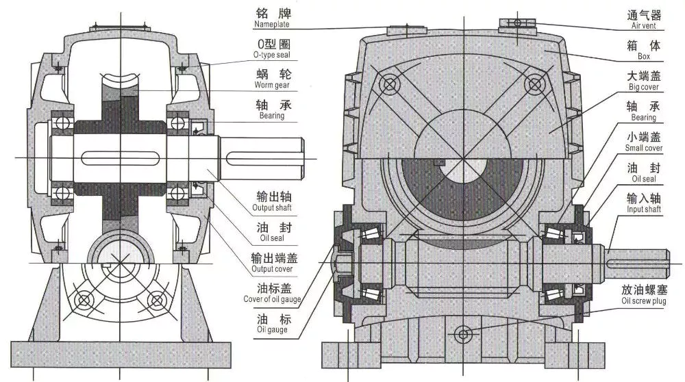
Worm reduction gearbox
The global worm reduction gearbox market report compiles key insights from the industry to help you improve your business strategy. This report will help you create a comprehensive business document that will enhance your company’s competitive edge. To obtain this report, visit our website now! Read our latest report to find out what you can expect from the global worm reduction gearbox market. Alternatively, request a sample copy for more details. Here is a sneak peek of the report:
Worm gears are made with different thread counts and are usually not matched with the CZPT standard. In general, a single thread worm should be used with a single thread worm. Worm gears have either right or left threads, and their thread count will be different as well. This type of gear is used to reduce the speed of a rotating shaft. The speed reduction ratio will be about 50 percent if the worms have the same thread count as the CZPT gears.
The standard gear set transfers power at the peak load point of a tooth, called the pitchline. The worm gear moves slowly against the wheel’s metal surface. The worm gear is also more complex than the standard gear because the worm is sliding rather than rolling. Worm gears are hard to lubricate. Moreover, the sliding contact between the gear and worm increases the complexity of the gear set. They can be a great solution for applications where noise is a significant factor.
The axial pitch and circular pitch of the worm are equal. The ratio of these two indices determines the speed of transmission. For a worm reduction gearbox to work, the axial pitch and the circular pitch must match. The pitch angle of a worm can either be left-handed or right-handed. The lead of a worm is the distance one thread travels in one revolution. The lead angle is the angle tangent to the thread helix of the cylinder’s pitch. When a worm mesh is reversed, the majority of the mesh will be on the receding arc.
Worm gears generate more heat than their counterparts, so it is important to choose a worm reduction gearbox carefully. You will want to choose the material and amount of lubricating oil carefully. Worm gears are generally made of tin bronze. The paired worms are hardened to HRC45-55. In general, they are durable, lasting up to ten years. But they will wear out – and they wear out – so you may want to consider some other factors.
Shaft-mounted gearbox
Shaft-mounted gearboxes are designed for a variety of mining and quarry applications. Their high reliability and low maintenance make them an excellent choice in these types of applications. Shaft-mounted gearboxes also feature an optional backstop device that prevents the unit from rotating in one direction. This makes them an excellent choice for applications where alignment accuracy is an issue. Here are some of the benefits of using a shaft-mounted gearbox:
Shaft-mounted gearboxes are typically constructed of aluminium, and come in sizes ranging from 050 to 125. They feature a variety of reduction ratios and ensure optimum efficiency in all operating conditions. New S series sizes, 140 and 150, extend the application range of shaft-mounted gearmotors. They are both backed by a two-year warranty. For even greater peace of mind, Shaft-mounted gearboxes are available with a range of warranty options.
The most common applications for a Shaft-mounted gearbox include traction-driven applications where a low-speed shaft is required for operation. They also are suitable for applications without a foundation, where the motor is mounted next to the reducer. To prevent the gear drive from rotating, a torque arm is attached between the motor and the shaft. Small-sized shaft-mounted gear drives are usually made without motor mount kits, which can make them an excellent choice for conveying light loads.
Another important feature of a Shaft-mounted gearbox is its mounting position. The reduced motion through the drive is redirected through the shaft, creating additional forces. These additional forces can affect the performance of the gearbox, causing vibrations and noise. Consequently, it is important to replace worn or damaged belts on a regular basis. Further, shaft-mounted gearboxes can be affected by problems with other components and amplify vibrations.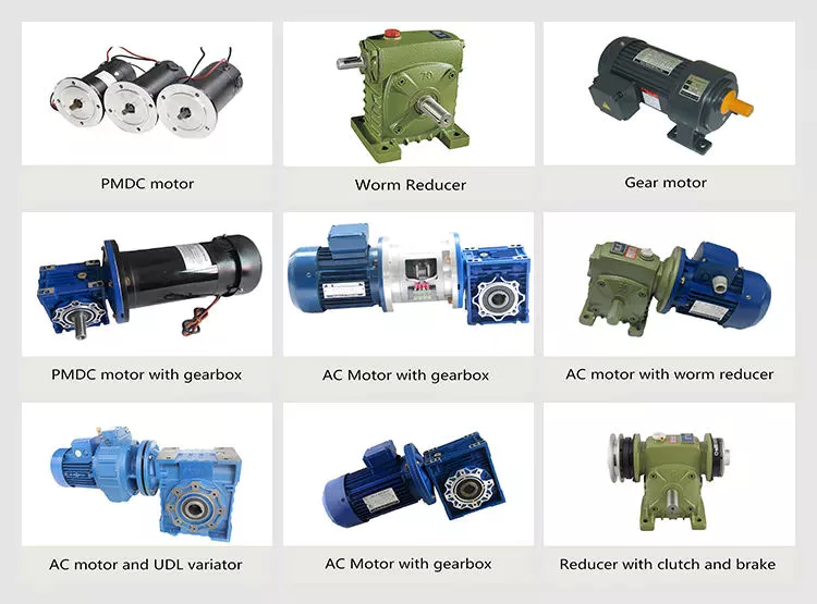
1 speed gearbox
CZPT Group Components produces one speed gearboxes. These transmissions are produced in the CZPT Group’s Kassel plant. They are compact and robust, and are designed for easy integration. The Bosch Rexroth GD1 one-speed gearbox is easy to install horizontally or vertically. The Plug and Drive system integrates the gearbox with the existing cooling system. There are many other benefits to this gearbox.
With an ID.3 electric drive motor, the maximum torque is delivered at 16,000 rpm. This single-speed transmission offers high power density and excellent noise-reduction, making it ideal for electric vehicles. The e-drive motor is extremely quiet and requires precision manufacturing. The e-drive motor also enables a wide range of driving conditions. It can reverse when needed, and reaches its maximum speed at 16,000.
The single-speed gearbox is a standard feature on most electric vehicles. Some electric vehicles, such as the Porsche Taycan, will be equipped with a two-speed gearbox. This gearbox offers more top speed and range, but it is more complex than a standard single-speed gearbox. CZPT doesn’t need to add complexity to its electric vehicles. After all, a 355 horsepower family wagon is not likely to need a dual-speed gearbox.
In addition to simplifying the transmission, the patent claims also address improvements in structural design. Fig. 5 shows a schematic representation of a transmission 50′, wherein gear sets Z1 and Z4 are exchanged between partial transmissions. This switch matrix also reflects the synchronized gears and lastshelf gears. Hydraulically betatigte Lamellenkupplungen (HBA) also form a last-shelf gear.
Another advantage of the patent claim is that it offers numerous functional freedoms, which is especially valuable in the design of an automobile. One of the patent claims identifies a tosatzlicher middle gear that allows a driver to switch between second and third gears, with a single gearbox. In a conventional one-speed transmission, the tosatzlicher middle gear is attached to the second and first part gearbox. The latter has a second and third gear.


editor by czh
China factory Low Noise Precision Servo Gearbox Spur Bevel Cycloidal Gear Planetary Speed Reducer Electric Motor Reductor Planetary Gearbox gearbox and motor
Warranty: 1 year
Applicable Industries: Manufacturing Plant, Food & Beverage Factory, Printing Shops, Energy & Mining, Other, Robotic
Weight (KG): 9
Customized support: OEM, ODM, OBM
Gearing Arrangement: Planetary
Output Torque: 40N.m~135N.m
Input Speed: 3500rpm~6000rpm
Product Name: Planetary Gearbox for nema 34 stepper motor
Application: Transmission Parts
Output Form: Solid
Protection Level: Protection Level
Life Time: 20000h
-25℃~+90℃: -25℃~+90℃
VGF Series Size: 60mm, 80mm, 120mm
Packaging Details: Precision Planetary Gearbox packed with Wooden Box & carton
Port: HangZhou
Product Overview
| Model | VGF60 | VGF85 | VGF115 | VGF160 |
| Size | 60mm | 80mm | 120mm | 130mm |
Key Market Insights Related to Worm Reduction Gearboxes
A gearbox is a mechanical device that allows you to shift between different speeds or gears. It does so by using one or more clutches. Some gearboxes are single-clutch, while others use two clutches. You can even find a gearbox with closed bladders. These are also known as dual clutches and can shift gears more quickly than other types. Performance cars are designed with these types of gearboxes.
Backlash measurement
Gearbox backlash is a common component that can cause noise or other problems in a car. In fact, the beats and sets of gears in a gearbox are often excited by the oscillations of the engine torque. Noise from gearboxes can be significant, particularly in secondary shafts that engage output gears with a differential ring. To measure backlash and other dimensional variations, an operator can periodically take the output shaft’s motion and compare it to a known value.
A comparator measures the angular displacement between two gears and displays the results. In one method, a secondary shaft is disengaged from the gearbox and a control gauge is attached to its end. A threaded pin is used to secure the differential crown to the secondary shaft. The output pinion is engaged with the differential ring with the aid of a control gauge. The angular displacement of the secondary shaft is then measured by using the dimensions of the output pinion.
Backlash measurements are important to ensure the smooth rotation of meshed gears. There are various types of backlash, which are classified according to the type of gear used. The first type is called circumferential backlash, which is the length of the pitch circle around which the gear rotates to make contact. The second type, angular backlash, is defined as the maximum angle of movement between two meshed gears, which allows the other gear to move when the other gear is stationary.
The backlash measurement for gearbox is one of the most important tests in the manufacturing process. It is a criterion of tightness or looseness in a gear set, and too much backlash can jam a gear set, causing it to interface on the weaker part of its gear teeth. When backlash is too tight, it can lead to gears jamming under thermal expansion. On the other hand, too much backlash is bad for performance.
Worm reduction gearboxes
Worm reduction gearboxes are used in the production of many different kinds of machines, including steel and power plants. They are also used extensively in the sugar and paper industries. The company is constantly aiming to improve their products and services to remain competitive in the global marketplace. The following is a summary of key market insights related to this type of gearbox. This report will help you make informed business decisions. Read on to learn more about the advantages of this type of gearbox.
Compared to conventional gear sets, worm reduction gearboxes have few disadvantages. Worm gear reducers are commonly available and manufacturers have standardized their mounting dimensions. There are no unique requirements for shaft length, height, and diameter. This makes them a very versatile piece of equipment. You can choose to use one or combine several worm gear reducers to fit your specific application. And because they have standardized ratios, you will not have to worry about matching up multiple gears and determining which ones fit.
One of the primary disadvantages of worm reduction gearboxes is their reduced efficiency. Worm reduction gearboxes usually have a maximum reduction ratio of five to sixty. The higher-performance hypoid gears have an output speed of around ten to twelve revolutions. In these cases, the reduced ratios are lower than those with conventional gearing. Worm reduction gearboxes are generally more efficient than hypoid gear sets, but they still have a low efficiency.
The worm reduction gearboxes have many advantages over traditional gearboxes. They are simple to maintain and can work in a range of different applications. Because of their reduced speed, they are perfect for conveyor belt systems.
Worm reduction gearboxes with closed bladders
The worm and the gear mesh with each other in a combination of sliding and rolling movements. This sliding action is dominant at high reduction ratios, and the worm and gear are made of dissimilar metals, which results in friction and heat. This limits the efficiency of worm gears to around thirty to fifty percent. A softer material for the gear can be used to absorb shock loads during operation.
A normal gear changes its output independently once a sufficient load is applied. However, the backstop complicates the gear configuration. Worm gears require lubrication because of the sliding wear and friction introduced during movement. A common gear arrangement moves power at the peak load section of a tooth. The sliding happens at low speeds on either side of the apex and occurs at a low velocity.
Single-reduction gearboxes with closed bladders may not require a drain plug. The reservoir for a worm gear reducer is designed so that the gears are in constant contact with lubricant. However, the closed bladders will cause the worm gear to wear out more quickly, which can cause premature wear and increased energy consumption. In this case, the gears can be replaced.
Worm gears are commonly used for speed reduction applications. Unlike conventional gear sets, worm gears have higher reduction ratios. The number of gear teeth in the worm reduces the speed of a particular motor by a substantial amount. This makes worm gears an attractive option for hoisting applications. In addition to their increased efficiency, worm gears are compact and less prone to mechanical failure.
Shaft arrangement of a gearbox
The ray-diagram of a gearbox shows the arrangement of gears in the various shafts of the transmission. It also shows how the transmission produces different output speeds from a single speed. The ratios that represent the speed of the spindle are called the step ratio and the progression. A French engineer named Charles Renard introduced five basic series of gearbox speeds. The first series is the gear ratio and the second series is the reverse gear ratio.
The layout of the gear axle system in a gearbox relates to its speed ratio. In general, the speed ratio and the centre distance are coupled by the gear axles to form an efficient transmission. Other factors that may affect the layout of the gear axles include space constraints, the axial dimension, and the stressed equilibrium. In October 2009, the inventors of a manual transmission disclosed the invention as No. 2. These gears can be used to realize accurate gear ratios.
The input shaft 4 in the gear housing 16 is arranged radially with the gearbox output shaft. It drives the lubricating oil pump 2. The pump draws oil from a filter and container 21. It then delivers the lubricating oil into the rotation chamber 3. The chamber extends along the longitudinal direction of the gearbox input shaft 4, and it expands to its maximum diameter. The chamber is relatively large, due to a detent 43.
Different configurations of gearboxes are based on their mounting. The mounting of gearboxes to the driven equipment dictates the arrangement of shafts in the gearbox. In certain cases, space constraints also affect the shaft arrangement. This is the reason why the input shaft in a gearbox may be offset horizontally or vertically. However, the input shaft is hollow, so that it can be connected to lead through lines or clamping sets.
Mounting of a gearbox
In the mathematical model of a gearbox, the mounting is defined as the relationship between the input and output shafts. This is also known as the Rotational Mount. It is one of the most popular types of models used for drivetrain simulation. This model is a simplified form of the rotational mount, which can be used in a reduced drivetrain model with physical parameters. The parameters that define the rotational mount are the TaiOut and TaiIn of the input and output shaft. The Rotational Mount is used to model torques between these two shafts.
The proper mounting of a gearbox is crucial for the performance of the machine. If the gearbox is not aligned properly, it may result in excessive stress and wear. It may also result in malfunctioning of the associated device. Improper mounting also increases the chances of the gearbox overheating or failing to transfer torque. It is essential to ensure that you check the mounting tolerance of a gearbox before installing it in a vehicle.


editor by czh