Product Description
INTRODUCTIN FOR GEARBOX TMG5713
1.Over view
The CHINAMFG 5713 type hydraulic transmission (hereinafter referred to as the transmission) consists of a YJH315 type hydraulic torque converter and a transmission with 4 CHINAMFG gears and 3 backward gears.
YJH315 The hydraulic torque converter is a single-stage two-phase integrated torque converter, with the characteristics of high efficiency and large torque change ratio. The gearbox is downshaft type, with the front 4 and rear 3 shift function, built-in working oil pump, external force port.
2. Main technical parameters
| Rated input power of the matching engine | 75kW |
| Rated input speed of the matching engine | 2400r / min |
| Input shaft steering (facing the transmission output) | counter clock wise |
| Working fluid | No.6 or No.8 hydraulic transmission oil |
| Main oil pressure and retaining oil pressure | 1.6MPa~1.9MPa |
| Torque converter oil inlet pressure | 0.4MPa~0.8MPa |
| Torque converter oil return pressure | 0.22MPa~0.4MPa |
| Working oil temperature | 80ºC ~100ºC |
| Rated voltage of the solenoid valve | DC24V |
About TMG
CHINAMFG is a professional trackless mining equipment, engineering equipment manufacturer.Our production base is located in HangZhou, ZheJiang .
Our products include: underground trackless mining equipment (underground loaders, underground mining trucks, utility vehicles, drill jumbos, drivetrain system transmission, torque converter, axle); engineering equipment ( wheel loaders, backhoe loaders, excavators, telescopic handlers,graders, articulated dump trucks); drive-train system (transmission, torque converter, axle).
Besides,as a technology oriented enterprise, we also provide customers with solutions including drive-train system customization, vehicle transformation and project contracting etc.
| Improvement | |||||||
| The torque converter is easy to heat up | |||||||
| Inability to climb hills | |||||||
| Climbing long slopes is prone to overheating | |||||||
| Punch | |||||||
| Easy to burn the friction plate | |||||||
| Loud noise | |||||||
| Cause Analysis | |||||||
| Small horse-drawn cart | |||||||
| The hydraulic flow of the charging oil is low and the pressure fluctuates greatly | |||||||
| Comparison with Top Euro brand | |||||||
| Customized design to solve customer pain points | |||||||
| Short lead time, 3 months | |||||||
| Electrically controlled shifting and automatic shifting mode are adopted to reduce shifting impact and protect gears from damage | |||||||
| Hydraulic torque converter has large circulation, large transmitted torque, large traction and strong climbing ability. Change | |||||||
| Torque is not easy to heat up. | |||||||
| The clutch structure is improved to reduce the friction plate burning phenomenon caused by the inaccurate control of the engagement time of the 2 clutches during the shifting process. | |||||||
| The gear is thickened to improve the reliability of the gearbox. Higher reliability and longer life. |
| Payload 6~7 ton Calculation details | ||||||||
| Diesel Engine Model | kW | Torque Converter |
Transmission | Traction kN | 1st km/h | 2nd km/h | 3rd km/h | 4th km/h |
| Deutz BF6M 1013EC165KW |
165 | YJ330 (C273.1) |
RC33429 | 175.53 | 4.87 | 9.68 | 18.28 | 25.66 |
| Deutz BF6M 1013EC165KW |
165 | YJ330 (C273.1) |
RC33428 | 178.74 | 4.79 | 9.52 | 17.97 | 24.57 |
| CUMMIS B67CS4 | 162 | YJ330 (C273.1) |
RC33429 | 156.47 | 4.84 | 9.63 | 17.12 | 25.04 |
| CUMMIS B67CS4 | 162 | YJ330 (C273.1) |
RC33428 | 166.15 | 4.56 | 9.08 | 17.19 | 23.59 |
| Volvo TAD850VE | 162 | YJ330 (C273.1) |
RC33429 | 159.71 | 5.06 | 10.28 | 18.82 | 27.53 |
| Volvo TAD850VE | 162 | YJ330 (C273.1) |
RC33428 | 169.57 | 4.76 | 9.44 | 17.72 | 24.11 |
/* January 22, 2571 19:08:37 */!function(){function s(e,r){var a,o={};try{e&&e.split(“,”).forEach(function(e,t){e&&(a=e.match(/(.*?):(.*)$/))&&1
| Application: | Machinery, Wheel Loader;Backhoe Loader |
|---|---|
| Function: | Change Drive Torque, Speed Changing, Speed Reduction, Speed Increase |
| Layout: | Cycloidal |
| Hardness: | Hardened Tooth Surface |
| Installation: | Horizontal Type |
| Step: | Four-Step |
| Customization: |
Available
| Customized Request |
|---|
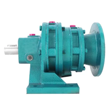
Efficiency of Cycloidal Gearboxes in Power Transmission
Cycloidal gearboxes offer relatively high power transmission efficiency compared to other types of gearboxes. The efficiency of a cycloidal gearbox depends on various factors, including the design, quality of components, lubrication, and load conditions.
Typically, the power transmission efficiency of a cycloidal gearbox ranges from 85% to 95%. However, this can vary based on several factors:
- Number of Reduction Stages: Multi-stage cycloidal gearboxes may experience slightly lower efficiency due to multiple gear meshing interactions.
- Quality and Design: Well-designed and precision-manufactured cycloidal gearboxes tend to exhibit higher efficiency.
- Lubrication: Proper lubrication is crucial for reducing friction and enhancing efficiency. Insufficient or deteriorated lubrication can lead to efficiency losses.
- Load Conditions: Higher loads and torque levels can lead to higher friction and lower efficiency. Properly matching the gearbox to the application is essential.
Despite minor efficiency losses compared to some other gearbox types, the benefits of compactness, high torque density, and precise motion control often outweigh the efficiency considerations in many applications.
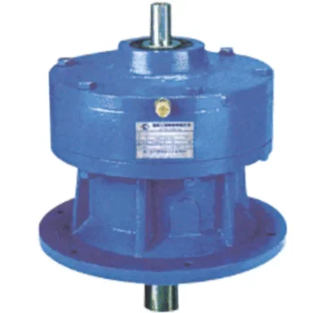
Maintenance Requirements for Cycloidal Gearboxes
Maintaining cycloidal gearboxes is essential to ensure their optimal performance and longevity. Here are some maintenance practices to consider:
- Lubrication: Regular lubrication is crucial to prevent wear and friction between moving parts. Use high-quality lubricants recommended by the gearbox manufacturer.
- Inspections: Regularly inspect the gearbox for signs of wear, damage, or oil leakage. Address any issues promptly to prevent further damage.
- Cleaning: Keep the gearbox clean and free from debris that could interfere with its operation. Cleanliness helps prevent contamination and wear.
- Torque Checks: Periodically check the tightness of fasteners and bolts to ensure they are properly secured. Loose fasteners can lead to misalignment and reduced performance.
- Seal Maintenance: Check and maintain seals to prevent oil leakage. Damaged seals should be replaced promptly to avoid lubricant loss.
- Temperature Monitoring: Monitor the operating temperature of the gearbox to ensure it remains within the recommended range. Excessive heat can lead to premature wear.
- Alignment: Ensure that the gearbox is properly aligned with other components to prevent misalignment-related issues.
- Regular Service: Follow the manufacturer’s recommended service intervals for more in-depth inspections and maintenance tasks.
Regular and proactive maintenance can extend the lifespan of cycloidal gearboxes, minimize downtime, and maintain their efficiency and performance over time.
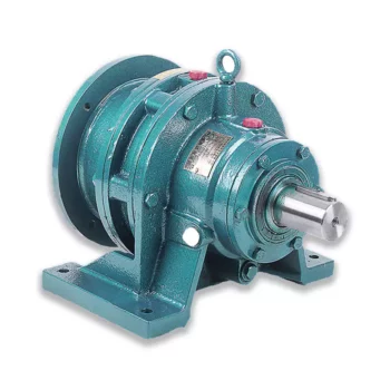
Principle of Cycloidal Gearing
Cycloidal gearing is a mechanism that utilizes the unique shape of cycloidal discs to achieve motion transmission. The principle involves the interaction between two main components: the input disc and the output disc.
The input disc has lobes with pins, while the output disc has lobes with matching holes. The lobes on both discs are not perfectly circular but are shaped in a cycloidal profile. As the input disc rotates, the pins on its lobes engage with the holes in the output disc’s lobes.
As the input disc rotates, the pins move along the cycloidal paths, causing the output disc to rotate. The interaction between the pins and the holes results in smooth and continuous motion transfer. The unique shape of the cycloidal profile ensures that there is always at least one point of contact between the pins and the holes, allowing for efficient torque transmission and reduced wear.
Cycloidal gearing provides advantages such as high torque capacity, compact size, and precision motion. However, due to the complex shape of the components and the continuous engagement, manufacturing and assembly of cycloidal gearboxes can be intricate.


editor by CX 2024-04-22
China Xb Cycloidal Pin Wheel Speed Gearbox Variator Drive Power Transmission Cycloidal Gearbox Gear Box Marine Engine with Gearbox with Good quality
Solution Description
X / B collection cycloidal gearbox speed reducer
Swift Particulars:
Variety: XB sequence Cycloidal Pin Wheel Speed Reducer
Input Speed: one thousand-1500rmp
Output Speed: .3-280rpm
Certification: ISO9001 CE
Ex Energy:.09-132KW
Guarantee: 1Years
|
Input Pace |
≤2000rpm |
|
Output Pace |
Single-phase:eleven-136rpm |
|
Energy Selection |
One-stage:.37-75Kw |
|
Assemble Type |
Foot-mounted horizontal and flange vertical |
|
Model |
Goldgun |
|
Ratio |
Solitary-stage:eleven,17,23,29,35,forty three,59,71,87 |
Associated Items
Firm Information
|
/ Piece | |
100 Pieces (Min. Order) |
###
| Application: | Motor, Electric Cars, Motorcycle, Machinery, Marine, Agricultural Machinery, Car |
|---|---|
| Function: | Distribution Power, Clutch, Change Drive Torque, Change Drive Direction, Speed Changing, Speed Reduction, Speed Increase |
| Layout: | Coaxial |
| Hardness: | Hardened Tooth Surface |
| Installation: | Horizontal Type |
| Step: | Three-Step |
###
| Samples: |
US$ 9999/Piece
1 Piece(Min.Order) |
|---|
###
|
Input Speed
|
≤2000rpm
|
|
Output Speed
|
Single-stage:11-136rpm
Two-stage:1.78-12.4rpm |
|
Power Range
|
Single-stage:0.37-75Kw
Two-stage:0.25-18.5Kw |
|
Assemble Type
|
Foot-mounted horizontal and flange vertical
|
|
Brand
|
Goldgun
|
|
Ratio
|
Single-stage:11,17,23,29,35,43,59,71,87
Two-stage:121,187,289,391,473,595,731,841,1003,1225,1505 |
|
/ Piece | |
100 Pieces (Min. Order) |
###
| Application: | Motor, Electric Cars, Motorcycle, Machinery, Marine, Agricultural Machinery, Car |
|---|---|
| Function: | Distribution Power, Clutch, Change Drive Torque, Change Drive Direction, Speed Changing, Speed Reduction, Speed Increase |
| Layout: | Coaxial |
| Hardness: | Hardened Tooth Surface |
| Installation: | Horizontal Type |
| Step: | Three-Step |
###
| Samples: |
US$ 9999/Piece
1 Piece(Min.Order) |
|---|
###
|
Input Speed
|
≤2000rpm
|
|
Output Speed
|
Single-stage:11-136rpm
Two-stage:1.78-12.4rpm |
|
Power Range
|
Single-stage:0.37-75Kw
Two-stage:0.25-18.5Kw |
|
Assemble Type
|
Foot-mounted horizontal and flange vertical
|
|
Brand
|
Goldgun
|
|
Ratio
|
Single-stage:11,17,23,29,35,43,59,71,87
Two-stage:121,187,289,391,473,595,731,841,1003,1225,1505 |
The Cyclonoidal Gearbox
Basically, the cycloidal gearbox is a gearbox that uses a cycloidal motion to perform its rotational movement. It is a very simple and efficient design that can be used in a variety of applications. A cycloidal gearbox is often used in applications that require the movement of heavy loads. It has several advantages over the planetary gearbox, including its ability to be able to handle higher loads and higher speeds.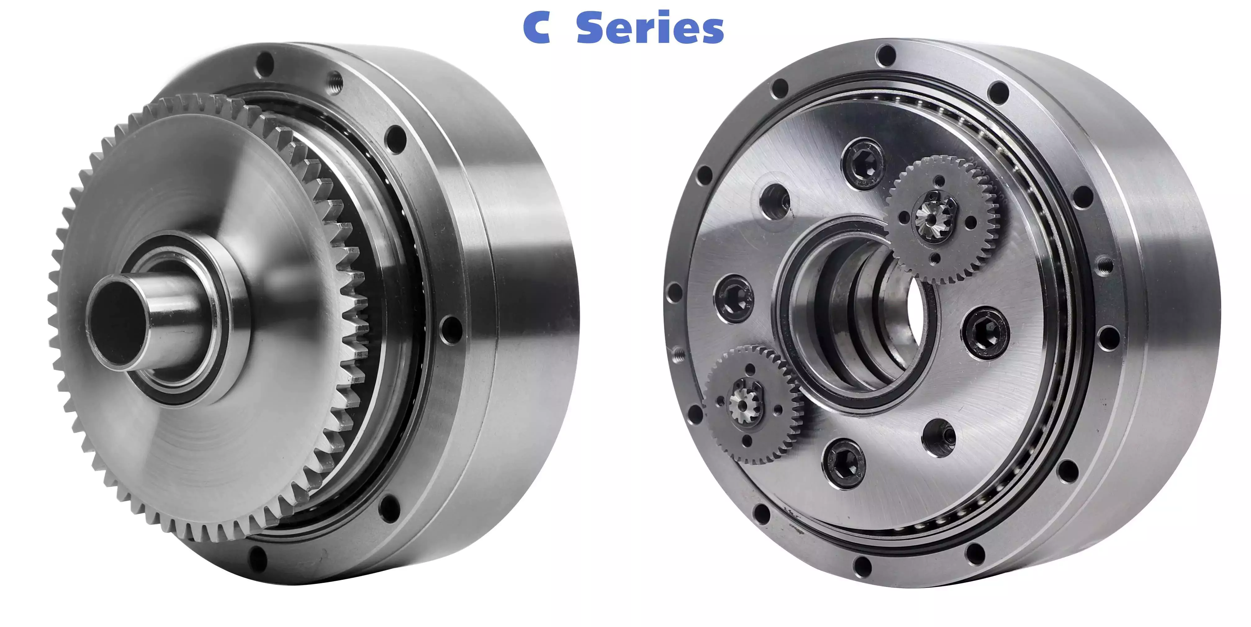
Dynamic and inertial effects of a cycloidal gearbox
Several studies have been conducted on the dynamic and inertial effects of a cycloidal gearbox. Some of them focus on operating principles, while others focus on the mathematical model of the gearbox. This paper examines the mathematical model of a cycloidal gearbox, and compares its performance with the real-world measurements. It is important to have a proper mathematical model to design and control a cycloidal gearbox. A cycloidal gearbox is a two-stage gearbox with a cycloid disc and a ring gear that revolves around its own axis.
The mathematical model is made up of more than 1.6 million elements. Each gear pair is represented by a reduced model with 500 eigenmodes. The eigenfrequency for the spur gear is 70 kHz. The modally reduced model is a good fit for the cycloidal gearbox.
The mathematical model is validated using ABAQUS software. A cycloid disc was discretized to produce a very fine model. It requires 400 element points per tooth. It was also verified using static FEA. This model was then used to model the stiction of the gears in all quadrants. This is a new approach to modelling stiction in a cycloidal gearbox. It has been shown to produce results comparable to those of the EMBS model. The results are also matched by the elastic multibody simulation model. This is a good fit for the contact forces and magnitude of the cycloid gear disc. It was also found that the transmission accuracy between the cycloid gear disc and the ring gear is about 98.5%. However, this value is lower than the transmission accuracy of the ring gear pair. The transmission error of the corrected model is about 0.3%. The transmission accuracy is less because of the lower amount of elastic deformation on the tooth flanks.
It is important to note that the most accurate contact forces for each tooth of a cycloid gearbox are not smooth. The contact force on a single tooth starts with a linear rise and then ends with a sharp drop. It is not as smooth as the contact force on a point contact, which is why it has been compared to the contact force on an ellipse contact. However, the contact on an ellipse contact is still relatively small, and the EMBS model is not able to capture this.
The FE model for the cycloid disc is about 1.6 million elements. The most important part of the FE model is the discretization of the cycloid disc. It is very important to do the discretization of the cycloid gear disc very carefully because of the high degree of vibration that it experiences. The cycloid disc has to be discretized finely so that the results are comparable to those of a static FEA. It has to be the most accurate model possible in order to be able to accurately simulate the contact forces between the cycloid disc and the ring gear.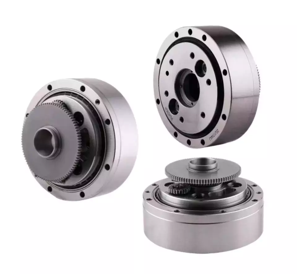
Kinematics of a cycloidal drive
Using an arbitrary coordinate system, we can observe the motion of components in a cycloidal gearbox. We observe that the cycloidal disc rotates around fixed pins in a circle, while the follower shaft rotates around the eccentric cam. In addition, we see that the input shaft is mounted eccentrically to the rolling-element bearing.
We also observe that the cycloidal disc rotates independently around the eccentric bearing, while the follower shaft rotates around an axis of symmetry. We can conclude that the cycloidal disc plays a pivotal role in the kinematics of a cycloidal gearbox.
To calculate the efficiency of the cycloidal reducer, we use a model that is based on the non-linear stiffness of the contacts. In this model, the non-linearity of the contact is governed by the non-linearity of the force and the deformation in the contact. We have shown that the efficiency of the cycloidal reducer increases as the load increases. In addition, the efficiency is dependent on the sliding velocity and the deformations of the normal load. These factors are considered as the key variables to determine the efficiency of the cycloidal drive.
We also consider the efficiency of the cycloidal reducer with the input torque and the input speed. We can calculate the efficiency by dividing the net torque in the ring gear by the output torque. The efficiency can be adjusted to suit different operating conditions. The efficiency of the cycloidal drive is increased as the load increases.
The cycloidal gearbox is a multi-stage gearbox with a small shaft oin and a big shaft. It has 19 teeth and brass washers. The outer discs move in opposition to the middle disc, and are offset by 180 deg. The middle disc is twice as massive as the outer disc. The cycloidal disc has nine lobes that move by one lobe per drive shaft revolution. The number of pins in the disc should be smaller than the number of pins in the surrounding pins.
The input shaft drives an eccentric bearing that is able to transmit the power to the output shaft. In addition, the input shaft applies forces to the cycloidal disk through the intermediate bearing. The cycloidal disk then advances in 360 deg/pivot/roller steps. The output shaft pins then move around in the holes to make the output shaft rotate continuously. The input shaft applies a sinusoidal motion to maintain the constant speed of the base shaft. This sine wave causes small adjustments to the follower shaft. The forces applied to the internal sleeves are a part of the equilibrium mechanism.
In addition, we can observe that the cycloidal drive is capable of transmitting a greater torque than the planetary gear. This is due to the cycloidal gear’s larger axial length and the ring gear’s smaller hole diameter. It is also possible to achieve a positive fit between the fixed ring and the disc, which is achieved by toothing between the fixed ring and the disc. The cycloidal disk is usually designed with a short cycloid to minimize unbalance forces at high speeds.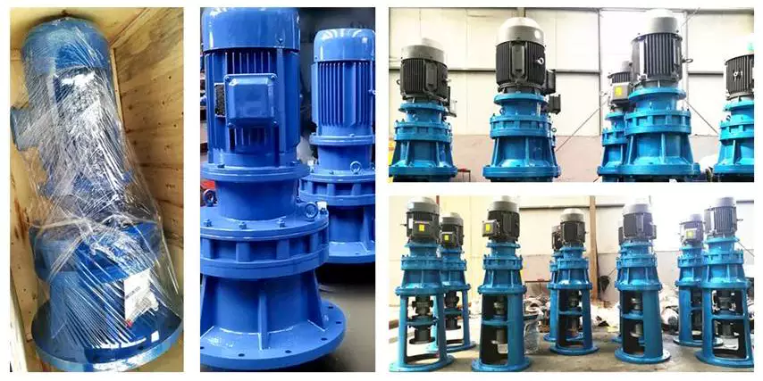
Comparison with planetary gearboxes
Compared to planetary gearboxes, the cycloidal gearbox has some advantages. These advantages include: low backlash, better overload capacity, a compact design, and the ability to perform in a wide range of applications. The cycloidal gearbox has become popular in the multi-axis robotics market. The gearbox is also increasingly used in first joints and positioners.
A cycloidal gearbox is a gearbox that consists of four basic components: a cycloid disk, an output flange, a ring gear, and a fixed ring. The cycloid disk is driven by an eccentric shaft, which advances in a 360deg/pivot/roller step. The output flange is a fixed pin disc that transmits the power to the output shaft. The ring gear is a fixed ring, and the input shaft is connected to a servomotor.
The cycloidal gearbox is designed to control inertia in highly dynamic situations. These gearboxes are generally used in robotics and positioners, where they are used to position heavy loads. They are also commonly used in a wide range of industrial applications. They have higher torque density and a low backlash, making them ideal for heavy loads.
The output flange is also designed to handle a torque of up to 500 Nm. Its rotational speed is lower than the planet gearbox, but its output torque is much higher. It is designed to be a high-performance gearbox, and it can be used in applications that need high ratios and a high level of torque density. The cycloid gearbox is also less expensive and has less backlash. However, the cycloidal gearbox has disadvantages that should be considered when designing a gearbox. The main problem is vibrations.
Compared to planetary gearboxes, cycloidal gearboxes have a smaller overall size and are less expensive. In addition, the cycloid gearbox has a large reduction ratio in one stage. In general, cycloidal gearboxes have single or two stages, with the third stage being less common. However, the cycloid gearbox is not the only type of gearbox that has this type of configuration. It is also common to find a planetary gearbox with a single stage.
There are several different types of cycloidal gearboxes, and they are often referred to as cycloidal speed reducers. These gearboxes are designed for any industry that uses servos. They are shorter than planetary gearboxes, and they are larger in diameter for the same torque. Some of them are also available with a ratio lower than 30:1.
The cycloid gearbox can be a good choice for applications where there are high rotational speeds and high torque requirements. These gearboxes are also more compact than planetary gearboxes, and are suitable for high-torque applications. In addition, they are more robust and can handle shock loads. They also have low backlash, and a higher level of accuracy and positioning accuracy. They are also used in a wide range of applications, including industrial robotics.

editor by CX 2023-03-27
China Industrial Robotic Arms gearbox rv robot reduction gearboxe diesel engine gear set eccentric reducer concentric reducer bevel gearbox
Relevant Industries: Resorts, Garment Retailers, Constructing Materials Shops, Manufacturing Plant, Machinery Mend Shops, Farms, Cafe, House Use, YZ91230 Boot Matches FOR JOHN DEERE TRACTOR Types 6603 Retail, Meals Shop, Printing Retailers, Construction works , Foodstuff & Beverage Shops, Marketing Business
Gearing Arrangement: Cycloidal
Output Torque: 65-34300N.m
Input Pace: 750-3000rpm
Output Pace: 5-60rpm
Ratio: 56-192
Packaging Details: Stanard picket situation, or wood pallet
Port: ZheJiang PORT / HangZhou PORT
Industrial Robotic Arms gearbox rv robotic reduction gearboxe
Software
Palletizing robot,rotating perform system, Manufacturing unit direct income Precision Equipment Linear Bearing Slide Block SC10VUU 10mm for CNC router 3D printer sorts of locator,robot joints,mahine instrument,medical apparatus and devices,ATC unit,AGV driver, lid change gear
E Sequence outline dimension drawing
120BX-E Outline Drawing
150BX-E Outline Drawing
190BX-E Outline Drawing
Certifications
Trade Displays
Packaging & Shipping
Firm Details
other collection item
| Precision Planetary gearbox | Robot RV gearbox speed reducer |
| Custom made Non-regular Gearbox | UDL Series Variator |
| PYZ Series Helical Tooth Shaft Mounted Reducer | 8000 Sequence Cycloidal Reducer |
| SLT Sequence Spiral Bevel Gearbox | SLSWL Collection Worm Screw Jack |
| SLP Series Planetary Reducer | SLH/SLB Sequence Substantial Power Reducer |
| NMRV Series Worm Reducer | BKM Collection Helical-hypoid Reducer |
| SLRC Series Helical Reducer | SLSMR Sequence Shaft Mounted Reducer |
| SLXG Series Shaft Mounted Reducer | X/B Series Cycloidal Reducer |
| SLR/SLF/SLK/SLS Sequence Helical Reducer |
Speak to
How to Select a Gearbox
When you drive your vehicle, the gearbox provides you with traction and speed. The lower gear provides the most traction, while the higher gear has the most speed. Selecting the right gear for your driving conditions will help you maximize both. The right gearing will vary based on road conditions, load, and speed. Short gearing will accelerate you more quickly, while tall gearing will increase top speed. However, you should understand how to use the gearbox before driving.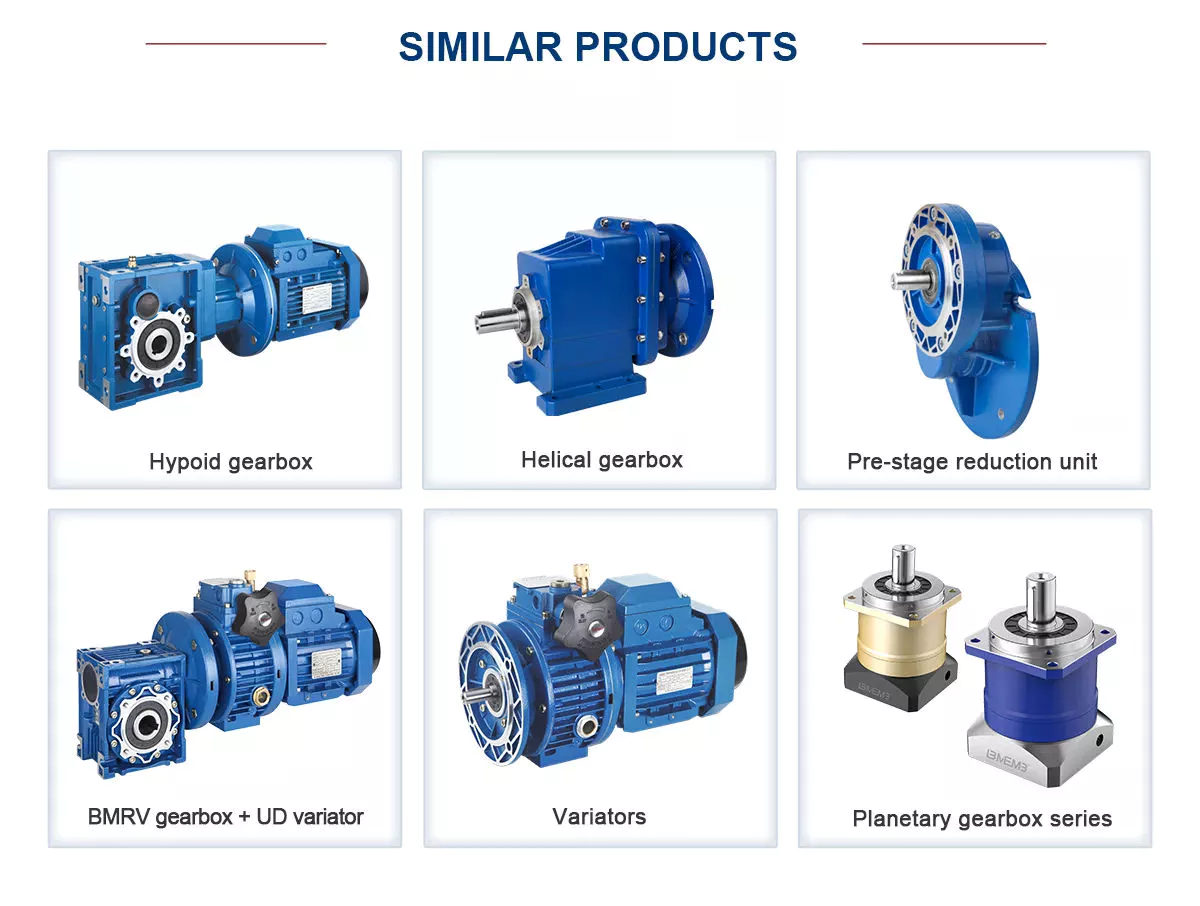
Function
The function of the gearbox is to transmit rotational energy to the machine’s drive train. The ratio between input and output torque is the ratio of the torque to the speed of rotation. Gearboxes have many different functions. A gearbox may have multiple functions or one function that is used to drive several other machines. If one gear is not turning, the other will be able to turn the gearbox. This is where the gearbox gets its name.
The pitch-controlled system has an equal number of failure modes as the electrical system, accounting for a large proportion of the longest machine downtime and halt time. The relationship between mechanisms and faults is not easily modeled mathematically. Failure modes of gearboxes are shown in Fig. 3. A gearbox’s true service life is six to eight years. However, a gearbox’s fault detection process must be developed as mature technology is required to reduce the downtime and avoid catastrophic incidents.
A gearbox is a vital piece of machinery. It processes energy produced by an engine to move the machine’s parts. A gearbox’s efficiency depends on how efficiently it transfers energy. The higher the ratio, the more torque is transferred to the wheels. It is a common component of bicycles, cars, and a variety of other devices. Its four major functions include:
In addition to ensuring gearbox reliability, a gearbox’s maintainability should be evaluated in the design phase. Maintainability considerations should be integrated into the gearbox design, such as the type of spare parts available. An appropriate maintenance regime will also determine how often to replace or repair specific parts. A proper maintenance procedure will also ensure that the gearbox is accessible. Whether it is easy to access or difficult to reach, accessibility is essential.
Purpose
A car’s transmission connects the engine to the wheels, allowing a higher-speed crankshaft to provide leverage. High-torque engines are necessary for the vehicle’s starting, acceleration, and meeting road resistance. The gearbox reduces the engine’s speed and provides torque variations at the wheels. The transmission also provides reversing power, making it possible to move the vehicle backwards and forwards.
Gears transmit power from one shaft to another. The size of the gears and number of teeth determine the amount of torque the unit can transmit. A higher gear ratio means more torque, but slower speed. The gearbox’s lever moves the engaging part on the shaft. The lever also slides the gears and synchronizers into place. If the lever slips to the left or right, the engine operates in second gear.
Gearboxes need to be closely monitored to reduce the likelihood of premature failure. Various tests are available to detect defective gear teeth and increase machine reliability. Figure 1.11(a) and (b) show a gearbox with 18 teeth and a 1.5:1 transmission ratio. The input shaft is connected to a sheave and drives a “V” belt. This transmission ratio allows the gearbox to reduce the speed of the motor, while increasing torque and reducing output speed.
When it comes to speed reduction, gear box is the most common method for reducing motor torque. The torque output is directly proportional to the volume of the motor. A small gearbox, for example, can produce as much torque as a large motor with the same output speed. The same holds true for the reverse. There are hybrid drives and in-line gearboxes. Regardless of the type, knowing about the functions of a gearbox will make it easier to choose the right one for your specific application.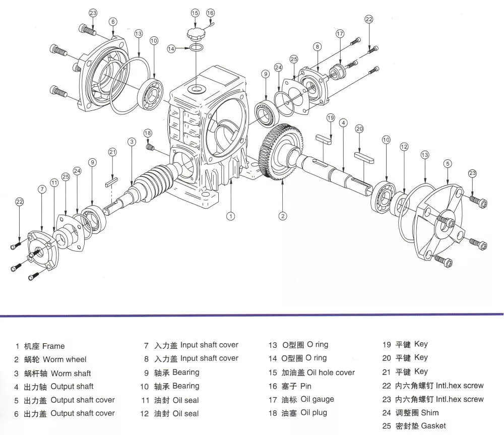
Application
When selecting a gearbox, the service factor must be considered. Service factor is the difference between the actual capacity of the gearbox and the value required by the application. Additional requirements for the gearbox may result in premature seal wear or overheating. The service factor should be as low as possible, as it could be the difference between the lifetime of the gearbox and its failure. In some cases, a gearbox’s service factor can be as high as 1.4, which is sufficient for most industrial applications.
China dominates the renewable energy industry, with the largest installed capacity of 1000 gigawatts and more than 2000 terawatt hours of electricity generated each year. The growth in these sectors is expected to increase the demand for gearboxes. For example, in China, wind and hydropower energy production are the major components of wind and solar power plants. The increased installation capacity indicates increased use of gearboxes for these industries. A gearbox that is not suitable for its application will not be functional, which may be detrimental to the production of products in the country.
A gearbox can be mounted in one of four different positions. The first three positions are concentric, parallel, or right angle, and the fourth position is shaft mount. A shaft mount gearbox is typically used in applications where the motor can’t be mounted via a foot. These positions are discussed in more detail below. Choosing the correct gearbox is essential in your business, but remember that a well-designed gearbox will help your bottom line.
The service factor of a gearbox is dependent on the type of load. A high shock load, for example, can cause premature failure of the gear teeth or shaft bearings. In such cases, a higher service factor is required. In other cases, a gearbox that is designed for high shock loads can withstand such loads without deteriorating its performance. Moreover, it will also reduce the cost of maintaining the gearbox over time.
Material
When choosing the material for your gearbox, you must balance the strength, durability, and cost of the design. This article will discuss the different types of materials and their respective applications and power transmission calculations. A variety of alloys are available, each of which offers its own advantages, including improved hardness and wear resistance. The following are some of the common alloys used in gears. The advantage of alloys is their competitive pricing. A gear made from one of these materials is usually stronger than its counterparts.
The carbon content of SPCC prevents the material from hardening like SS. However, thin sheets made from SPCC are often used for gears with lower strength. Because of the low carbon content, SPCC’s surface doesn’t harden as quickly as SS gears do, so soft nitriding is needed to provide hardness. However, if you want a gear that won’t rust, then you should consider SS or FCD.
In addition to cars, gearboxes are also used in the aerospace industry. They are used in space travel and are used in airplane engines. In agriculture, they are used in irrigation, pest and insect control machinery, and plowing machines. They are also used in construction equipment like cranes, bulldozers, and tractors. Gearboxes are also used in the food processing industry, including conveyor systems, kilns, and packaging machinery.
The teeth of the gears in your gearbox are important when it comes to performance. A properly meshing gear will allow the gears to achieve peak performance and withstand torque. Gear teeth are like tiny levers, and effective meshing reduces stress and slippage. A stationary parametric analysis will help you determine the quality of meshing throughout the gearing cycle. This method is often the most accurate way to determine whether your gears are meshing well.
Manufacturing
The global gear market is divided into five key regions, namely, North America, Europe, Asia Pacific, and Latin America. Among these regions, Asia Pacific is expected to generate the largest GDP, owing to rapidly growing energy demand and investments in industrial infrastructure. This region is also home to some of the largest manufacturing bases, and its continuous building of new buildings and homes will support the industry’s growth. In terms of application, gearboxes are used in construction, agricultural machinery, and transportation.
The Industrial Gearbox market is anticipated to expand during the next several years, driven by the rapid growth of the construction industry and business advancements. However, there are several challenges that hamper the growth of the industry. These include the high cost of operations and maintenance of gear units. This report covers the market size of industrial gearboxes globally, as well as their manufacturing technologies. It also includes manufacturer data for the period of 2020-2024. The report also features a discussion of market drivers and restraints.
Global health crisis and decreasing seaborne commerce have moderately adverse effects on the industry. Falling seaborne commerce has created a barrier to investment. The value of international crude oil is expected to cross USD 0 by April 2020, putting an end to new assets development and exploitation. In such a scenario, the global gearbox market will face many challenges. However, the opportunities are huge. So, the market for industrial gearboxes is expected to grow by more than 6% by 2020, thanks to the increasing number of light vehicles sold in the country.
The main shaft of a gearbox, also known as the output shaft, spins at different speeds and transfers torque to an automobile. The output shaft is splined so that a coupler and gear can be connected to it. The counter shaft and primary shaft are supported by bearings, which reduce friction in the spinning element. Another important part of a gearbox is the gears, which vary in tooth count. The number of teeth determines how much torque a gear can transfer. In addition, the gears can glide in any position.


editor by czh 2023-02-17