Product Description
INTRODUCTIN FOR GEARBOX TMG5713
1.Over view
The CHINAMFG 5713 type hydraulic transmission (hereinafter referred to as the transmission) consists of a YJH315 type hydraulic torque converter and a transmission with 4 CHINAMFG gears and 3 backward gears.
YJH315 The hydraulic torque converter is a single-stage two-phase integrated torque converter, with the characteristics of high efficiency and large torque change ratio. The gearbox is downshaft type, with the front 4 and rear 3 shift function, built-in working oil pump, external force port.
2. Main technical parameters
| Rated input power of the matching engine | 75kW |
| Rated input speed of the matching engine | 2400r / min |
| Input shaft steering (facing the transmission output) | counter clock wise |
| Working fluid | No.6 or No.8 hydraulic transmission oil |
| Main oil pressure and retaining oil pressure | 1.6MPa~1.9MPa |
| Torque converter oil inlet pressure | 0.4MPa~0.8MPa |
| Torque converter oil return pressure | 0.22MPa~0.4MPa |
| Working oil temperature | 80ºC ~100ºC |
| Rated voltage of the solenoid valve | DC24V |
About TMG
CHINAMFG is a professional trackless mining equipment, engineering equipment manufacturer.Our production base is located in HangZhou, ZheJiang .
Our products include: underground trackless mining equipment (underground loaders, underground mining trucks, utility vehicles, drill jumbos, drivetrain system transmission, torque converter, axle); engineering equipment ( wheel loaders, backhoe loaders, excavators, telescopic handlers,graders, articulated dump trucks); drive-train system (transmission, torque converter, axle).
Besides,as a technology oriented enterprise, we also provide customers with solutions including drive-train system customization, vehicle transformation and project contracting etc.
| Improvement | |||||||
| The torque converter is easy to heat up | |||||||
| Inability to climb hills | |||||||
| Climbing long slopes is prone to overheating | |||||||
| Punch | |||||||
| Easy to burn the friction plate | |||||||
| Loud noise | |||||||
| Cause Analysis | |||||||
| Small horse-drawn cart | |||||||
| The hydraulic flow of the charging oil is low and the pressure fluctuates greatly | |||||||
| Comparison with Top Euro brand | |||||||
| Customized design to solve customer pain points | |||||||
| Short lead time, 3 months | |||||||
| Electrically controlled shifting and automatic shifting mode are adopted to reduce shifting impact and protect gears from damage | |||||||
| Hydraulic torque converter has large circulation, large transmitted torque, large traction and strong climbing ability. Change | |||||||
| Torque is not easy to heat up. | |||||||
| The clutch structure is improved to reduce the friction plate burning phenomenon caused by the inaccurate control of the engagement time of the 2 clutches during the shifting process. | |||||||
| The gear is thickened to improve the reliability of the gearbox. Higher reliability and longer life. |
| Payload 6~7 ton Calculation details | ||||||||
| Diesel Engine Model | kW | Torque Converter |
Transmission | Traction kN | 1st km/h | 2nd km/h | 3rd km/h | 4th km/h |
| Deutz BF6M 1013EC165KW |
165 | YJ330 (C273.1) |
RC33429 | 175.53 | 4.87 | 9.68 | 18.28 | 25.66 |
| Deutz BF6M 1013EC165KW |
165 | YJ330 (C273.1) |
RC33428 | 178.74 | 4.79 | 9.52 | 17.97 | 24.57 |
| CUMMIS B67CS4 | 162 | YJ330 (C273.1) |
RC33429 | 156.47 | 4.84 | 9.63 | 17.12 | 25.04 |
| CUMMIS B67CS4 | 162 | YJ330 (C273.1) |
RC33428 | 166.15 | 4.56 | 9.08 | 17.19 | 23.59 |
| Volvo TAD850VE | 162 | YJ330 (C273.1) |
RC33429 | 159.71 | 5.06 | 10.28 | 18.82 | 27.53 |
| Volvo TAD850VE | 162 | YJ330 (C273.1) |
RC33428 | 169.57 | 4.76 | 9.44 | 17.72 | 24.11 |
/* January 22, 2571 19:08:37 */!function(){function s(e,r){var a,o={};try{e&&e.split(“,”).forEach(function(e,t){e&&(a=e.match(/(.*?):(.*)$/))&&1
| Application: | Machinery, Wheel Loader;Backhoe Loader |
|---|---|
| Function: | Change Drive Torque, Speed Changing, Speed Reduction, Speed Increase |
| Layout: | Cycloidal |
| Hardness: | Hardened Tooth Surface |
| Installation: | Horizontal Type |
| Step: | Four-Step |
| Customization: |
Available
| Customized Request |
|---|

Efficiency of Cycloidal Gearboxes in Power Transmission
Cycloidal gearboxes offer relatively high power transmission efficiency compared to other types of gearboxes. The efficiency of a cycloidal gearbox depends on various factors, including the design, quality of components, lubrication, and load conditions.
Typically, the power transmission efficiency of a cycloidal gearbox ranges from 85% to 95%. However, this can vary based on several factors:
- Number of Reduction Stages: Multi-stage cycloidal gearboxes may experience slightly lower efficiency due to multiple gear meshing interactions.
- Quality and Design: Well-designed and precision-manufactured cycloidal gearboxes tend to exhibit higher efficiency.
- Lubrication: Proper lubrication is crucial for reducing friction and enhancing efficiency. Insufficient or deteriorated lubrication can lead to efficiency losses.
- Load Conditions: Higher loads and torque levels can lead to higher friction and lower efficiency. Properly matching the gearbox to the application is essential.
Despite minor efficiency losses compared to some other gearbox types, the benefits of compactness, high torque density, and precise motion control often outweigh the efficiency considerations in many applications.

Maintenance Requirements for Cycloidal Gearboxes
Maintaining cycloidal gearboxes is essential to ensure their optimal performance and longevity. Here are some maintenance practices to consider:
- Lubrication: Regular lubrication is crucial to prevent wear and friction between moving parts. Use high-quality lubricants recommended by the gearbox manufacturer.
- Inspections: Regularly inspect the gearbox for signs of wear, damage, or oil leakage. Address any issues promptly to prevent further damage.
- Cleaning: Keep the gearbox clean and free from debris that could interfere with its operation. Cleanliness helps prevent contamination and wear.
- Torque Checks: Periodically check the tightness of fasteners and bolts to ensure they are properly secured. Loose fasteners can lead to misalignment and reduced performance.
- Seal Maintenance: Check and maintain seals to prevent oil leakage. Damaged seals should be replaced promptly to avoid lubricant loss.
- Temperature Monitoring: Monitor the operating temperature of the gearbox to ensure it remains within the recommended range. Excessive heat can lead to premature wear.
- Alignment: Ensure that the gearbox is properly aligned with other components to prevent misalignment-related issues.
- Regular Service: Follow the manufacturer’s recommended service intervals for more in-depth inspections and maintenance tasks.
Regular and proactive maintenance can extend the lifespan of cycloidal gearboxes, minimize downtime, and maintain their efficiency and performance over time.

Principle of Cycloidal Gearing
Cycloidal gearing is a mechanism that utilizes the unique shape of cycloidal discs to achieve motion transmission. The principle involves the interaction between two main components: the input disc and the output disc.
The input disc has lobes with pins, while the output disc has lobes with matching holes. The lobes on both discs are not perfectly circular but are shaped in a cycloidal profile. As the input disc rotates, the pins on its lobes engage with the holes in the output disc’s lobes.
As the input disc rotates, the pins move along the cycloidal paths, causing the output disc to rotate. The interaction between the pins and the holes results in smooth and continuous motion transfer. The unique shape of the cycloidal profile ensures that there is always at least one point of contact between the pins and the holes, allowing for efficient torque transmission and reduced wear.
Cycloidal gearing provides advantages such as high torque capacity, compact size, and precision motion. However, due to the complex shape of the components and the continuous engagement, manufacturing and assembly of cycloidal gearboxes can be intricate.


editor by CX 2024-04-22
China best Cycloidal Gearbox Cyclo Gear Box Drive Motor Speed Reducer Gearboxes Planetary CZPT Power Industrial Transmission Best Price Manufacture Cycloidal Gearbox automatic gearbox
Product Description
Cycloidal gearbox cyclo gear box drive motor speed reducer gearboxes planetary CHINAMFG power industrial transmission best price manufacture Cycloidal gearbox
X / B series high quality cycloidal gearbox small planetary reducer
Quick Details:
Type: XB series Cycloidal Pin Wheel Speed Reducer
Input Speed: 1000-1500rmp
Output Speed: 0.3-280rpm
Certification: ISO9001 CE
Ex Power:0.09-132KW
Warranty: 1Years
| Product Name | X/B series Cycloidal Pin Wheel Speed Reducer |
| The Gear Material | GCR15 |
| The case Material | Cast Iron |
| Color | Blue,Green, or Customized |
| HS Code | 84834090 |
| Model | X3 |
| Delivery time | 7-10days |
| Brand | TIANGOU |
| Application: | Motor, Machinery, Agricultural Machinery |
|---|---|
| Function: | Distribution Power, Speed Reduction, Speed Increase |
| Layout: | Cycloidal |
| Hardness: | Hardened Tooth Surface |
| Installation: | Vertical Type |
| Step: | Stepless |
| Samples: |
US$ 9999/Piece
1 Piece(Min.Order) | |
|---|

Variations in Cycloidal Gearbox Design
Cycloidal gearboxes come in various designs and configurations to cater to different application requirements. Some common variations include:
- Single-Stage vs. Multi-Stage: Cycloidal gearboxes can be designed as single-stage or multi-stage systems. Single-stage designs offer a lower gear ratio and are suitable for applications with moderate torque requirements. Multi-stage designs provide higher gear ratios and are used for applications demanding higher torque output.
- Input and Output Arrangements: Cycloidal gearboxes can have various input and output arrangements, including coaxial, inline, and right-angle configurations. These arrangements determine the orientation of the input and output shafts relative to each other.
- Size and Torque Capacity: Different sizes of cycloidal gearboxes are available to accommodate a wide range of torque and power requirements. Smaller sizes are suitable for applications where space is limited, while larger sizes handle higher torque loads.
- Mounting Options: Cycloidal gearboxes offer flexibility in mounting options, including base or flange mounting. This allows for easy integration into different types of machinery and equipment.
- Material Selection: Depending on the application’s demands, cycloidal gearboxes can be constructed using various materials, such as steel, aluminum, and alloys. Material selection affects the gearbox’s durability and performance in different environments.
- Backlash Reduction Mechanisms: Some cycloidal gearboxes feature enhanced backlash reduction mechanisms to further improve precision and accuracy in motion control applications.
These variations in design allow cycloidal gearboxes to be tailored to specific application requirements, making them versatile solutions for a wide range of industries and machinery.
Maintenance Requirements for Cycloidal Gearboxes
Maintaining cycloidal gearboxes is essential to ensure their optimal performance and longevity. Here are some maintenance practices to consider:
- Lubrication: Regular lubrication is crucial to prevent wear and friction between moving parts. Use high-quality lubricants recommended by the gearbox manufacturer.
- Inspections: Regularly inspect the gearbox for signs of wear, damage, or oil leakage. Address any issues promptly to prevent further damage.
- Cleaning: Keep the gearbox clean and free from debris that could interfere with its operation. Cleanliness helps prevent contamination and wear.
- Torque Checks: Periodically check the tightness of fasteners and bolts to ensure they are properly secured. Loose fasteners can lead to misalignment and reduced performance.
- Seal Maintenance: Check and maintain seals to prevent oil leakage. Damaged seals should be replaced promptly to avoid lubricant loss.
- Temperature Monitoring: Monitor the operating temperature of the gearbox to ensure it remains within the recommended range. Excessive heat can lead to premature wear.
- Alignment: Ensure that the gearbox is properly aligned with other components to prevent misalignment-related issues.
- Regular Service: Follow the manufacturer’s recommended service intervals for more in-depth inspections and maintenance tasks.
Regular and proactive maintenance can extend the lifespan of cycloidal gearboxes, minimize downtime, and maintain their efficiency and performance over time.

Common Applications of Cycloidal Gearboxes
Cycloidal gearboxes find their application in various industries and scenarios where their unique features are advantageous:
- Robotics: Cycloidal gearboxes are often used in robotic joints and manipulators due to their compact size, high torque capacity, and precision movement.
- Conveyor Systems: Their ability to handle heavy loads and provide accurate motion makes cycloidal gearboxes suitable for conveyor systems in industries such as manufacturing, food processing, and material handling.
- Aerospace: In aerospace applications, cycloidal gearboxes are used in satellite mechanisms, aerospace actuators, and precision motion control systems.
- Medical Devices: The compact design and precise motion capabilities of cycloidal gearboxes are beneficial in medical equipment such as surgical robots and diagnostic devices.
- Textile Industry: Cycloidal gearboxes are utilized in textile machines for their ability to provide accurate and synchronized movement in the weaving and knitting processes.
- Automotive: Some automotive applications, such as sunroof mechanisms and power seats, can benefit from the compact size and high torque capacity of cycloidal gearboxes.
- Printing Industry: The precision and reliability of cycloidal gearboxes are important in printing presses to ensure accurate paper feeding and positioning.
- Packaging Machinery: In packaging equipment, cycloidal gearboxes can provide the required torque and accuracy for tasks like sealing, labeling, and filling.
These are just a few examples of where cycloidal gearboxes are commonly used, demonstrating their versatility and adaptability across various industries.
editor by CX 2023-12-01
China Xb Cycloidal Pin Wheel Speed Gearbox Variator Drive Power Transmission Cycloidal Gearbox Gear Box Marine Engine with Gearbox with Good quality
Solution Description
X / B collection cycloidal gearbox speed reducer
Swift Particulars:
Variety: XB sequence Cycloidal Pin Wheel Speed Reducer
Input Speed: one thousand-1500rmp
Output Speed: .3-280rpm
Certification: ISO9001 CE
Ex Energy:.09-132KW
Guarantee: 1Years
|
Input Pace |
≤2000rpm |
|
Output Pace |
Single-phase:eleven-136rpm |
|
Energy Selection |
One-stage:.37-75Kw |
|
Assemble Type |
Foot-mounted horizontal and flange vertical |
|
Model |
Goldgun |
|
Ratio |
Solitary-stage:eleven,17,23,29,35,forty three,59,71,87 |
Associated Items
Firm Information
|
/ Piece | |
100 Pieces (Min. Order) |
###
| Application: | Motor, Electric Cars, Motorcycle, Machinery, Marine, Agricultural Machinery, Car |
|---|---|
| Function: | Distribution Power, Clutch, Change Drive Torque, Change Drive Direction, Speed Changing, Speed Reduction, Speed Increase |
| Layout: | Coaxial |
| Hardness: | Hardened Tooth Surface |
| Installation: | Horizontal Type |
| Step: | Three-Step |
###
| Samples: |
US$ 9999/Piece
1 Piece(Min.Order) |
|---|
###
|
Input Speed
|
≤2000rpm
|
|
Output Speed
|
Single-stage:11-136rpm
Two-stage:1.78-12.4rpm |
|
Power Range
|
Single-stage:0.37-75Kw
Two-stage:0.25-18.5Kw |
|
Assemble Type
|
Foot-mounted horizontal and flange vertical
|
|
Brand
|
Goldgun
|
|
Ratio
|
Single-stage:11,17,23,29,35,43,59,71,87
Two-stage:121,187,289,391,473,595,731,841,1003,1225,1505 |
|
/ Piece | |
100 Pieces (Min. Order) |
###
| Application: | Motor, Electric Cars, Motorcycle, Machinery, Marine, Agricultural Machinery, Car |
|---|---|
| Function: | Distribution Power, Clutch, Change Drive Torque, Change Drive Direction, Speed Changing, Speed Reduction, Speed Increase |
| Layout: | Coaxial |
| Hardness: | Hardened Tooth Surface |
| Installation: | Horizontal Type |
| Step: | Three-Step |
###
| Samples: |
US$ 9999/Piece
1 Piece(Min.Order) |
|---|
###
|
Input Speed
|
≤2000rpm
|
|
Output Speed
|
Single-stage:11-136rpm
Two-stage:1.78-12.4rpm |
|
Power Range
|
Single-stage:0.37-75Kw
Two-stage:0.25-18.5Kw |
|
Assemble Type
|
Foot-mounted horizontal and flange vertical
|
|
Brand
|
Goldgun
|
|
Ratio
|
Single-stage:11,17,23,29,35,43,59,71,87
Two-stage:121,187,289,391,473,595,731,841,1003,1225,1505 |
The Cyclonoidal Gearbox
Basically, the cycloidal gearbox is a gearbox that uses a cycloidal motion to perform its rotational movement. It is a very simple and efficient design that can be used in a variety of applications. A cycloidal gearbox is often used in applications that require the movement of heavy loads. It has several advantages over the planetary gearbox, including its ability to be able to handle higher loads and higher speeds.
Dynamic and inertial effects of a cycloidal gearbox
Several studies have been conducted on the dynamic and inertial effects of a cycloidal gearbox. Some of them focus on operating principles, while others focus on the mathematical model of the gearbox. This paper examines the mathematical model of a cycloidal gearbox, and compares its performance with the real-world measurements. It is important to have a proper mathematical model to design and control a cycloidal gearbox. A cycloidal gearbox is a two-stage gearbox with a cycloid disc and a ring gear that revolves around its own axis.
The mathematical model is made up of more than 1.6 million elements. Each gear pair is represented by a reduced model with 500 eigenmodes. The eigenfrequency for the spur gear is 70 kHz. The modally reduced model is a good fit for the cycloidal gearbox.
The mathematical model is validated using ABAQUS software. A cycloid disc was discretized to produce a very fine model. It requires 400 element points per tooth. It was also verified using static FEA. This model was then used to model the stiction of the gears in all quadrants. This is a new approach to modelling stiction in a cycloidal gearbox. It has been shown to produce results comparable to those of the EMBS model. The results are also matched by the elastic multibody simulation model. This is a good fit for the contact forces and magnitude of the cycloid gear disc. It was also found that the transmission accuracy between the cycloid gear disc and the ring gear is about 98.5%. However, this value is lower than the transmission accuracy of the ring gear pair. The transmission error of the corrected model is about 0.3%. The transmission accuracy is less because of the lower amount of elastic deformation on the tooth flanks.
It is important to note that the most accurate contact forces for each tooth of a cycloid gearbox are not smooth. The contact force on a single tooth starts with a linear rise and then ends with a sharp drop. It is not as smooth as the contact force on a point contact, which is why it has been compared to the contact force on an ellipse contact. However, the contact on an ellipse contact is still relatively small, and the EMBS model is not able to capture this.
The FE model for the cycloid disc is about 1.6 million elements. The most important part of the FE model is the discretization of the cycloid disc. It is very important to do the discretization of the cycloid gear disc very carefully because of the high degree of vibration that it experiences. The cycloid disc has to be discretized finely so that the results are comparable to those of a static FEA. It has to be the most accurate model possible in order to be able to accurately simulate the contact forces between the cycloid disc and the ring gear.
Kinematics of a cycloidal drive
Using an arbitrary coordinate system, we can observe the motion of components in a cycloidal gearbox. We observe that the cycloidal disc rotates around fixed pins in a circle, while the follower shaft rotates around the eccentric cam. In addition, we see that the input shaft is mounted eccentrically to the rolling-element bearing.
We also observe that the cycloidal disc rotates independently around the eccentric bearing, while the follower shaft rotates around an axis of symmetry. We can conclude that the cycloidal disc plays a pivotal role in the kinematics of a cycloidal gearbox.
To calculate the efficiency of the cycloidal reducer, we use a model that is based on the non-linear stiffness of the contacts. In this model, the non-linearity of the contact is governed by the non-linearity of the force and the deformation in the contact. We have shown that the efficiency of the cycloidal reducer increases as the load increases. In addition, the efficiency is dependent on the sliding velocity and the deformations of the normal load. These factors are considered as the key variables to determine the efficiency of the cycloidal drive.
We also consider the efficiency of the cycloidal reducer with the input torque and the input speed. We can calculate the efficiency by dividing the net torque in the ring gear by the output torque. The efficiency can be adjusted to suit different operating conditions. The efficiency of the cycloidal drive is increased as the load increases.
The cycloidal gearbox is a multi-stage gearbox with a small shaft oin and a big shaft. It has 19 teeth and brass washers. The outer discs move in opposition to the middle disc, and are offset by 180 deg. The middle disc is twice as massive as the outer disc. The cycloidal disc has nine lobes that move by one lobe per drive shaft revolution. The number of pins in the disc should be smaller than the number of pins in the surrounding pins.
The input shaft drives an eccentric bearing that is able to transmit the power to the output shaft. In addition, the input shaft applies forces to the cycloidal disk through the intermediate bearing. The cycloidal disk then advances in 360 deg/pivot/roller steps. The output shaft pins then move around in the holes to make the output shaft rotate continuously. The input shaft applies a sinusoidal motion to maintain the constant speed of the base shaft. This sine wave causes small adjustments to the follower shaft. The forces applied to the internal sleeves are a part of the equilibrium mechanism.
In addition, we can observe that the cycloidal drive is capable of transmitting a greater torque than the planetary gear. This is due to the cycloidal gear’s larger axial length and the ring gear’s smaller hole diameter. It is also possible to achieve a positive fit between the fixed ring and the disc, which is achieved by toothing between the fixed ring and the disc. The cycloidal disk is usually designed with a short cycloid to minimize unbalance forces at high speeds.
Comparison with planetary gearboxes
Compared to planetary gearboxes, the cycloidal gearbox has some advantages. These advantages include: low backlash, better overload capacity, a compact design, and the ability to perform in a wide range of applications. The cycloidal gearbox has become popular in the multi-axis robotics market. The gearbox is also increasingly used in first joints and positioners.
A cycloidal gearbox is a gearbox that consists of four basic components: a cycloid disk, an output flange, a ring gear, and a fixed ring. The cycloid disk is driven by an eccentric shaft, which advances in a 360deg/pivot/roller step. The output flange is a fixed pin disc that transmits the power to the output shaft. The ring gear is a fixed ring, and the input shaft is connected to a servomotor.
The cycloidal gearbox is designed to control inertia in highly dynamic situations. These gearboxes are generally used in robotics and positioners, where they are used to position heavy loads. They are also commonly used in a wide range of industrial applications. They have higher torque density and a low backlash, making them ideal for heavy loads.
The output flange is also designed to handle a torque of up to 500 Nm. Its rotational speed is lower than the planet gearbox, but its output torque is much higher. It is designed to be a high-performance gearbox, and it can be used in applications that need high ratios and a high level of torque density. The cycloid gearbox is also less expensive and has less backlash. However, the cycloidal gearbox has disadvantages that should be considered when designing a gearbox. The main problem is vibrations.
Compared to planetary gearboxes, cycloidal gearboxes have a smaller overall size and are less expensive. In addition, the cycloid gearbox has a large reduction ratio in one stage. In general, cycloidal gearboxes have single or two stages, with the third stage being less common. However, the cycloid gearbox is not the only type of gearbox that has this type of configuration. It is also common to find a planetary gearbox with a single stage.
There are several different types of cycloidal gearboxes, and they are often referred to as cycloidal speed reducers. These gearboxes are designed for any industry that uses servos. They are shorter than planetary gearboxes, and they are larger in diameter for the same torque. Some of them are also available with a ratio lower than 30:1.
The cycloid gearbox can be a good choice for applications where there are high rotational speeds and high torque requirements. These gearboxes are also more compact than planetary gearboxes, and are suitable for high-torque applications. In addition, they are more robust and can handle shock loads. They also have low backlash, and a higher level of accuracy and positioning accuracy. They are also used in a wide range of applications, including industrial robotics.

editor by CX 2023-03-27
China WPWDKT compact worm gearbox spiral bevel helical gear box power transmission electronic variator chinese reducer cycloidal gearbox
Gearing Arrangement: Worm
Output Torque: 1.8-2430N.M
Enter Speed: fourteen.2 bearing taper roller bearing F-237542.02 a hundred and twenty,135,147,155, FT800A.forty one.143 PTO connecting bolt For CZPT Lovol Agricultural Genuine tractor Spare Components Farm Tractors 175,200,250
Packaging Information: Wood bins , Cantons packed in 1 pallet
Port: ZheJiang /HangZhou Port
WPWDKT compact worm gearbox spiral bevel helical gear box electrical power transmission digital variator chinese reducer
Certifications
Trade Displays
Packaging & HXHV LMB8 UU 12 Inch Linear Bushing Ball Bearing With Size twelve.7×22.225×31.75mm ShippingPacking Particulars : Regular carton/Pallet/Standard wood circumstance
Supply Specifics : 15-30 operating days on payment
Business Info
other sequence solution
| Precision Planetary gearbox | Robotic RV gearbox speed reducer |
| Customized produced Non-standard Gearbox | UDL Collection Variator |
| PYZ Series Helical Tooth Shaft Mounted Reducer | 8000 Collection Cycloidal Reducer |
| SLT Series Spiral Bevel Gearbox | SLSWL Sequence Worm Screw Jack |
| SLP Series Planetary Reducer | SLH/SLB Series Substantial Power Reducer |
| NMRV Series Worm Reducer | BKM Series Helical-hypoid Reducer |
| SLRC Collection Helical Reducer | SLSMR Series Shaft Mounted Reducer |
| SLXG Series Shaft Mounted Reducer | X/B Series Cycloidal Reducer |
| SLR/SLF/SLK/SLS Series Helical Reducer |
Contact
What Is a Gearbox?
There are several factors to consider when choosing a gearbox. Backlash, for example, is a consideration, as it is the angle at which the output shaft can rotate without the input shaft moving. While this isn’t necessary in applications without load reversals, it is important for precision applications involving load reversals. Examples of these applications include automation and robotics. If backlash is a concern, you may want to look at other factors, such as the number of teeth in each gear.
Function of a gearbox
A gearbox is a mechanical unit that consists of a chain or set of gears. The gears are mounted on a shaft and are supported by rolling element bearings. These devices alter the speed or torque of the machine they are used in. Gearboxes can be used for a wide variety of applications. Here are some examples of how gearboxes function. Read on to discover more about the gears that make up a gearbox.
Regardless of the type of transmission, most gearboxes are equipped with a secondary gear and a primary one. While the gear ratios are the same for both the primary and secondary transmission, the gearboxes may differ in size and efficiency. High-performance racing cars typically employ a gearbox with two green and one blue gear. Gearboxes are often mounted in the front or rear of the engine.
The primary function of a gearbox is to transfer torque from one shaft to another. The ratio of the driving gear’s teeth to the receiving member determines how much torque is transmitted. A large gear ratio will cause the main shaft to revolve at a slower speed and have a high torque compared to its counter shaft. Conversely, a low gear ratio will allow the vehicle to turn at a lower speed and produce a lower torque.
A conventional gearbox has input and output gears. The countershaft is connected to a universal shaft. The input and output gears are arranged to match the speed and torque of each other. The gear ratio determines how fast a car can go and how much torque it can generate. Most conventional transmissions use four gear ratios, with one reverse gear. Some have two shafts and three inputs. However, if the gear ratios are high, the engine will experience a loss of torque.
In the study of gearbox performance, a large amount of data has been collected. A highly ambitious segmentation process has yielded nearly 20,000 feature vectors. These results are the most detailed and comprehensive of all the available data. This research has a dual curse – the first is the large volume of data collected for the purpose of characterization, while the second is the high dimensionality. The latter is a complication that arises when the experimental gearbox is not designed to perform well.
Bzvacklash
The main function of a gearhead is to multiply a moment of force and create a mechanical advantage. However, backlash can cause a variety of issues for the system, including impaired positioning accuracy and lowered overall performance. A zero backlash gearbox can eliminate motion losses caused by backlash and improve overall system performance. Here are some common problems associated with backlash in gearheads and how to fix them. After you understand how to fix gearbox backlash, you’ll be able to design a machine that meets your requirements.
To reduce gearbox backlash, many designers try to decrease the center distance of the gears. This eliminates space for lubrication and promotes excessive tooth mesh, which leads to premature mesh failure. To minimize gearbox backlash, a gear manufacturer may separate the two parts of the gear and adjust the mesh center distance between them. To do this, rotate one gear with respect to the fixed gear, while adjusting the other gear’s effective tooth thickness.
Several manufacturing processes may introduce errors, and reducing tooth thickness will minimize this error. Gears with bevel teeth are a prime example of this. This type of gear features a small number of teeth in comparison to its mating gear. In addition to reducing tooth thickness, bevel gears also reduce backlash. While bevel gears have fewer teeth than their mating gear, all of their backlash allowance is applied to the larger gear.
A gear’s backlash can affect the efficiency of a gearbox. In an ideal gear, the backlash is zero. But if there is too much, backlash can cause damage to the gears and cause it to malfunction. Therefore, the goal of gearbox backlash is to minimize this problem. However, this may require the use of a micrometer. To determine how much gearbox backlash you need, you can use a dial gauge or feeler gauge.
If you’ve been looking for a way to reduce backlash, a gearbox’s backlash may be the answer. However, backlash is not a revolt against the manufacturer. It is an error in motion that occurs naturally in gear systems that change direction. If it is left unaccounted for, it can lead to major gear degradation and even compromise the entire system. In this article, we’ll explain how backlash affects gears and how it affects the performance of a gearbox.
Design
The design of gearboxes consists of a variety of factors, including the type of material used, power requirements, speed and reduction ratio, and the application for which the unit is intended. The process of designing a gearbox usually begins with a description of the machine or gearbox and its intended use. Other key parameters to consider during gearbox design include the size and weight of the gear, its overall gear ratio and number of reductions, as well as the lubrication methods used.
During the design process, the customer and supplier will participate in various design reviews. These include concept or initial design review, manufacturing design validation, critical design review, and final design review. The customer may also initiate the process by initiating a DFMEA. After receiving the initial design approval, the design will go through several iterations before the finalized design is frozen. In some cases, the customer will require a DFMEA of the gearbox.
The speed increaser gearboxes also require special design considerations. These gearboxes typically operate at high speeds, causing problems with gear dynamics. Furthermore, the high speeds of the unit increase frictional and drag forces. A proper design of this component should minimize the effect of these forces. To solve these problems, a gearbox should incorporate a brake system. In some cases, an external force may also increase frictional forces.
Various types of gear arrangements are used in gearboxes. The design of the teeth of the gears plays a significant role in defining the type of gear arrangement in the gearbox. Spur gear is an example of a gear arrangement, which has teeth that run parallel to the axis of rotation. These gears offer high gear ratios and are often used in multiple stages. So, it is possible to create a gearbox that meets the needs of your application.
The design of gearboxes is the most complex process in the engineering process. These complex devices are made of multiple types of gears and are mounted on shafts. They are supported by rolling element bearings and are used for a variety of applications. In general, a gearbox is used to reduce speed and torque and change direction. Gearboxes are commonly used in motor vehicles, but can also be found in pedal bicycles and fixed machines.
Manufacturers
There are several major segments in the gearbox market, including industrial, mining, and automotive. Gearbox manufacturers are required to understand the application and user industries to design a gearbox that meets their specific requirements. Basic knowledge of metallurgy is necessary. Multinational companies also provide gearbox solutions for the power generation industry, shipping industry, and automotive industries. To make their products more competitive, they need to focus on product innovation, geographical expansion, and customer retention.
The CZPT Group started as a small company in 1976. Since then, it has become a global reference in mechanical transmissions. Its production range includes gears, reduction gearboxes, and geared motors. The company was the first in Italy to achieve ISO certification, and it continues to grow into one of the world’s leading manufacturers of production gearboxes. As the industry evolves, CZPT focuses on research and development to create better products.
The agriculture industry uses gearboxes to implement a variety of processes. They are used in tractors, pumps, and agricultural machinery. The automotive industry uses gears in automobiles, but they are also found in mining and tea processing machinery. Industrial gearboxes also play an important role in feed and speed drives. The gearbox industry has a diverse portfolio of manufacturers and suppliers. Here are some examples of gearboxes:
Gearboxes are complex pieces of equipment. They must be used properly to optimize efficiency and extend their lifespan. Manufacturers employ advanced technology and strict quality control processes to ensure their products meet the highest standards. In addition to manufacturing precision and reliability, gearbox manufacturers ensure that their products are safe for use in the production of industrial machinery. They are also used in office machines and medical equipment. However, the automotive gearbox market is becoming increasingly competitive.
editor by czh 2023-02-17
China Dongfeng Captain Transmission gear box assembly 17G0AD-DR03 gearbox adjustment
Applicable Industries: Producing Plant, Equipment Restore Shops, Design works , Vitality & Mining
Gearing Arrangement: Cycloidal
Output Torque: 800~100000N.m
Input Velocity: 1400rpm
Output Pace: fourteen-280rpm
Materials: Metallic
Kind: 17G0AD-DR03
Colour: Picture
Vehicle Make: Xihu (West Lake) Dis.feng
Solution title: Gearbox assembly
OEM: Accpet
Title: gearbox
Application: Automotive Elements
Dimension: OEM Normal Size
Certificate: ISO9001/TS16949
Packaging Details: Xihu (West Lake) Dis.feng Captain Transmission equipment box assembly 17G0AD-DR03 1.First 2.Normal 3.Customized
Port: ZheJiang , HangZhou ,HangZhou
| Working daily life | 6 monthes | Payment conditions | T/T |
| Colour | photo | Software | Vehicle engine |
| Automobile make | Duolika/Captain | Certification | ISO |
| Motor product | Kummins | Guarantee | two several years |
| Item Identify | Xihu (West Lake) Dis.feng gearbox | Operate | gearbox components |
| Element NO. | 17G0AD-DR03 | MOQ | one Piece |
| Package deal | Authentic & Nature | Value | USD760-780 |
| Shipping and delivery time | 5 days | Port | HangZhou/HangZhou/ZheJiang |
Technical specsone.Offer to Mid-east, Russia and Africa2.Matrial:Metal3.Professional Perfomance Automobile parts supplier 4.CZPT Engines
Comprehensive Images Connected Items Packing&Transport Our most skilled packaging Transport of big vehicles to the seaport And global transport cooperationCompany Introduction HangZhou Meiche Industrial & Trade Co., Ltd. is located in China’ CNC Equipment Aluminum Round Linear Motion Slide Device Bearing SBR16UU s greatest “Truck Town” called HangZhou. We are a skilled company of Xihu (West Lake) Dis.feng truck parts and DCEC, CCEC, FCEC, XCEC engine spare elements, include 4BT, 6BT, 6CT, ISDE, ISLE, M11, LG2 Leaded bronze bush, C83600 CNC machined solid bronze basic bearing, OEM BC6 gunmetal bush bronze bush bearing manufacturing unit L10, QSM, QSC.set layout, advancement, production as a skilled manufacturer.We target on a sequence of trend add-ons, a extensive variety of diversity, affordable value and on-time shipping and delivery. Our Service1. OEM Manufacturing welcome: Merchandise, Package… 2. Sample order 3. We will reply you for your inquiry in 24 hours.4. right after sending, we will track the merchandise for you as soon as each 2 times, till you get the goods. When you obtained the MAD M40 C30 Professional 43KV higher thrust and effective brushless drone motor for agriculture multirotor with 47X13.1 IN PROP products, take a look at them, and give me a feedback.If you have any questions about the difficulty, contact with us, we will offer the fix way for you.FAQQ1. Can you create according to the samples?A: Indeed, we can make by your samples or complex drawings. We can construct the molds and fixtures.Q1. What is your sample policy?A: We can offer the sample if we have all set elements in inventory, but the customers have to pay out the sample value and the courier expense.Q3. Do you test all your goods prior to shipping?A: Sure, we have 100% test just before deliveryQ4: How do you make our organization lengthy-phrase and great partnership?A:1. We maintain great good quality and aggressive cost to ensure our consumers benefit 2. We respect each and every consumer as our buddy and we sincerely do organization and make close friends with them, Durable Spindle motor 3000-12000 RPM Brush dc motors 775 150W lawn mower motor with 2 ball bearing Rated no subject where they arrive from.
What Is a Gearbox?
There are several factors to consider when choosing a gearbox. Backlash, for example, is a consideration, as it is the angle at which the output shaft can rotate without the input shaft moving. While this isn’t necessary in applications without load reversals, it is important for precision applications involving load reversals. Examples of these applications include automation and robotics. If backlash is a concern, you may want to look at other factors, such as the number of teeth in each gear.
Function of a gearbox
A gearbox is a mechanical unit that consists of a chain or set of gears. The gears are mounted on a shaft and are supported by rolling element bearings. These devices alter the speed or torque of the machine they are used in. Gearboxes can be used for a wide variety of applications. Here are some examples of how gearboxes function. Read on to discover more about the gears that make up a gearbox.
Regardless of the type of transmission, most gearboxes are equipped with a secondary gear and a primary one. While the gear ratios are the same for both the primary and secondary transmission, the gearboxes may differ in size and efficiency. High-performance racing cars typically employ a gearbox with two green and one blue gear. Gearboxes are often mounted in the front or rear of the engine.
The primary function of a gearbox is to transfer torque from one shaft to another. The ratio of the driving gear’s teeth to the receiving member determines how much torque is transmitted. A large gear ratio will cause the main shaft to revolve at a slower speed and have a high torque compared to its counter shaft. Conversely, a low gear ratio will allow the vehicle to turn at a lower speed and produce a lower torque.
A conventional gearbox has input and output gears. The countershaft is connected to a universal shaft. The input and output gears are arranged to match the speed and torque of each other. The gear ratio determines how fast a car can go and how much torque it can generate. Most conventional transmissions use four gear ratios, with one reverse gear. Some have two shafts and three inputs. However, if the gear ratios are high, the engine will experience a loss of torque.
In the study of gearbox performance, a large amount of data has been collected. A highly ambitious segmentation process has yielded nearly 20,000 feature vectors. These results are the most detailed and comprehensive of all the available data. This research has a dual curse – the first is the large volume of data collected for the purpose of characterization, while the second is the high dimensionality. The latter is a complication that arises when the experimental gearbox is not designed to perform well.
Bzvacklash
The main function of a gearhead is to multiply a moment of force and create a mechanical advantage. However, backlash can cause a variety of issues for the system, including impaired positioning accuracy and lowered overall performance. A zero backlash gearbox can eliminate motion losses caused by backlash and improve overall system performance. Here are some common problems associated with backlash in gearheads and how to fix them. After you understand how to fix gearbox backlash, you’ll be able to design a machine that meets your requirements.
To reduce gearbox backlash, many designers try to decrease the center distance of the gears. This eliminates space for lubrication and promotes excessive tooth mesh, which leads to premature mesh failure. To minimize gearbox backlash, a gear manufacturer may separate the two parts of the gear and adjust the mesh center distance between them. To do this, rotate one gear with respect to the fixed gear, while adjusting the other gear’s effective tooth thickness.
Several manufacturing processes may introduce errors, and reducing tooth thickness will minimize this error. Gears with bevel teeth are a prime example of this. This type of gear features a small number of teeth in comparison to its mating gear. In addition to reducing tooth thickness, bevel gears also reduce backlash. While bevel gears have fewer teeth than their mating gear, all of their backlash allowance is applied to the larger gear.
A gear’s backlash can affect the efficiency of a gearbox. In an ideal gear, the backlash is zero. But if there is too much, backlash can cause damage to the gears and cause it to malfunction. Therefore, the goal of gearbox backlash is to minimize this problem. However, this may require the use of a micrometer. To determine how much gearbox backlash you need, you can use a dial gauge or feeler gauge.
If you’ve been looking for a way to reduce backlash, a gearbox’s backlash may be the answer. However, backlash is not a revolt against the manufacturer. It is an error in motion that occurs naturally in gear systems that change direction. If it is left unaccounted for, it can lead to major gear degradation and even compromise the entire system. In this article, we’ll explain how backlash affects gears and how it affects the performance of a gearbox.
Design
The design of gearboxes consists of a variety of factors, including the type of material used, power requirements, speed and reduction ratio, and the application for which the unit is intended. The process of designing a gearbox usually begins with a description of the machine or gearbox and its intended use. Other key parameters to consider during gearbox design include the size and weight of the gear, its overall gear ratio and number of reductions, as well as the lubrication methods used.
During the design process, the customer and supplier will participate in various design reviews. These include concept or initial design review, manufacturing design validation, critical design review, and final design review. The customer may also initiate the process by initiating a DFMEA. After receiving the initial design approval, the design will go through several iterations before the finalized design is frozen. In some cases, the customer will require a DFMEA of the gearbox.
The speed increaser gearboxes also require special design considerations. These gearboxes typically operate at high speeds, causing problems with gear dynamics. Furthermore, the high speeds of the unit increase frictional and drag forces. A proper design of this component should minimize the effect of these forces. To solve these problems, a gearbox should incorporate a brake system. In some cases, an external force may also increase frictional forces.
Various types of gear arrangements are used in gearboxes. The design of the teeth of the gears plays a significant role in defining the type of gear arrangement in the gearbox. Spur gear is an example of a gear arrangement, which has teeth that run parallel to the axis of rotation. These gears offer high gear ratios and are often used in multiple stages. So, it is possible to create a gearbox that meets the needs of your application.
The design of gearboxes is the most complex process in the engineering process. These complex devices are made of multiple types of gears and are mounted on shafts. They are supported by rolling element bearings and are used for a variety of applications. In general, a gearbox is used to reduce speed and torque and change direction. Gearboxes are commonly used in motor vehicles, but can also be found in pedal bicycles and fixed machines.
Manufacturers
There are several major segments in the gearbox market, including industrial, mining, and automotive. Gearbox manufacturers are required to understand the application and user industries to design a gearbox that meets their specific requirements. Basic knowledge of metallurgy is necessary. Multinational companies also provide gearbox solutions for the power generation industry, shipping industry, and automotive industries. To make their products more competitive, they need to focus on product innovation, geographical expansion, and customer retention.
The CZPT Group started as a small company in 1976. Since then, it has become a global reference in mechanical transmissions. Its production range includes gears, reduction gearboxes, and geared motors. The company was the first in Italy to achieve ISO certification, and it continues to grow into one of the world’s leading manufacturers of production gearboxes. As the industry evolves, CZPT focuses on research and development to create better products.
The agriculture industry uses gearboxes to implement a variety of processes. They are used in tractors, pumps, and agricultural machinery. The automotive industry uses gears in automobiles, but they are also found in mining and tea processing machinery. Industrial gearboxes also play an important role in feed and speed drives. The gearbox industry has a diverse portfolio of manufacturers and suppliers. Here are some examples of gearboxes:
Gearboxes are complex pieces of equipment. They must be used properly to optimize efficiency and extend their lifespan. Manufacturers employ advanced technology and strict quality control processes to ensure their products meet the highest standards. In addition to manufacturing precision and reliability, gearbox manufacturers ensure that their products are safe for use in the production of industrial machinery. They are also used in office machines and medical equipment. However, the automotive gearbox market is becoming increasingly competitive.
editor by czh 2023-02-16
China Cast Iron Cycloidal pinwheel transmission reduce box ratio 29 china gear gearbox speed reducer with Great quality
Warranty: 3 several years, 1 Yr
Applicable Industries: Development works , Energy & Mining, Other
Tailored help: OEM
Gearing Arrangement: Cycloidal
Output Torque: 2.6-1195N.M
Input Speed: 3Quality: Nicely and substantial quality handle.MOQ: Offer you sample screening for distributor more amount, far better price.
All is with additional plastic bag to safeguard from damp surroundings.Cartons or wood cases with custom-made shipping and delivery marks or ad marks are offered. Inspected: All of our products are gel-coated and highly inspected before shipping and delivery.
Seperate picket cases112 body and previously mentioned is with wooden case package deal Cartons on wood palletsCartons for under 112 frame, with foam or wothout foam is each available. Our Service Payment Phrases:T/T acknowledge: FOB typically 30% deposit ,the harmony want to accepted prior to shipment CIF: The balance can be compensated when you see duplicate of the Invoice of LadingOthers L/C,W/U, MIGHTY’s Locking ring components clampingShaft collar clamping aspects with solitary double splits D/P, Paypal suitable.Shipping Time: 7~10days for samples, twenty five~30days for get soon after we get the deposit.
Types of Gearboxes
There are several types of gearboxes. Some are known as helical gear reducers, while others are called planetary gearboxes. The article also discusses Continuously Variable Transmission (CVT) and helical gear reducer. If you are interested in purchasing a new gearbox, make sure to read our articles on these different types. If you are confused, consider reading our articles on planetary gearboxes and helical gear reducers.
planetary gearbox
The planetary gearbox has several advantages. Its compact design and light weight allows it to transmit high torques while remaining quiet. The gears are connected to one another through a carrier, which is typically fixed and helps transmit torques to the output shaft. Its planetary structure arrangement also reduces backlash and provides high rigidity, which is important for quick start and stop cycles and rotational direction change. Depending on the design and performance desired, planetary gearboxes are categorized into three main types:
The type of planetary gears used in a given application determines the overall cost of the unit. Manufacturers offer a range of prices, and they can help you determine which gearbox is right for your needs. You should also ask a manufacturer for the cost of a planetary gearbox. By asking about price and specs, you can avoid wasting money and time on a planetary gearbox that does not perform up to its potential.
A planetary gearbox is probably installed in your new car’s automatic transmission. For more information, consult your owner’s manual or call the dealer’s service department. This type of gearbox is more complex than other types of gearboxes, so if you don’t know much about them, do an internet search for “planetary gearbox.”
The teeth of a planetary gearbox are formed by the stepping motion of two gears: the sun gear and the inner ring. The sun gear is the input, while the planetary gears rotate around the sun gear. Their ratio depends on the number of teeth and the space between the planets. If you have a 24 tooth sun gear, the planetary gears’ ratio will be -3/2. The sun gear is also attached to the axle.
Another advantage of a planetary gear system is that it can generate high torques. The load is shared among multiple planet gears. This makes the gears more resilient to damage. A planetary gearbox can be as high as 332,000 Nm, and can be used in vehicles and industrial applications requiring medium to high torque. A planetary gear system is a great alternative to a traditional transmission. So, how does it work?
helical gearbox
The main difference between the helical gearbox and the spur gear is the center distance between the teeth. The helical gearbox has a larger pitch circle than the spur gear and thus requires a radial module. In addition, the two types of gears can only be made with the same tooth-cutting tool as the spur gear. However, the helical gearbox is more efficient in terms of production costs.
The helical gearbox is a low-power consumption, compact type of gearbox that is used for a wide range of industrial applications. They are highly durable and withstand high loads with utmost efficiency. The helical gearbox can be manufactured in cast steel and iron for small and medium units. This type of gearbox is also commonly used for crushers, conveyors, coolers, and other applications that need low power.
The helical gear has many advantages over the spur gear. It produces less noise. It has less friction and is less likely to wear out. It is also quieter than spur gears. This is because multiple teeth are in mesh. Because the teeth are in mesh, the load is distributed over a larger area, resulting in a smoother transition between gears. The reduction in noise and vibration reduces the risk of damaging the gear.
The helical gear’s axial excitation force is obtained using a linearized equation of motion in the rotational direction. The damping coefficient of the equation is 0.07. The helical gear is made up of a steel shaft with a diameter of 20 mm and a 5 mm thick aluminum plate. The stiffness of the bearing is 6.84 x 10⁷ N/m. The damping force of the plate is 2,040 kg/m2/s.
The worm gearbox has a better efficiency ratio than the helical one, but it is less efficient in low-ratio applications. In general, worm gearboxes are more efficient than helical gearboxes, although there are some exceptions to this rule. A helical gearbox is better for applications that require high torque. It may also be more economical in the long run. If you are considering a helical gearbox, consider the advantages it has over worm gearboxes.
helical gear reducer
A helical gear reducer for a machine’s gearbox is an integral component of the drive system. This unit amplifies torque and controls speed and, therefore, compliments the engine by rotating slower than the engine’s input shaft. A helical gear reducer is a compact gearbox component that is used in industrial applications. A variety of sizes is available to suit various machine configurations. The following sections will discuss some of the different types available.
Designed by experts and engineers, a helical gear reducer is a surprisingly small and light gear that satisfies the needs of many machine applications. It features a large transmission torque, a low starting and running speed, and a fine classification of transmission ratios. A helical gear reducer is lightweight and easily connected to other gears, and it features a high technical content.
In order to avoid errors and poor performance, regular maintenance is a must. The proper lubrication of the gear reducer can minimize failures, errors, and poor performance. Every gear reducer manufacturer sells a suitable lubricant, which must match the properties of the machine’s drive mechanism. It is also advisable to check the lubrication regularly to avoid any deterioration of the unit’s performance.
While the worm gearbox may be better for applications where torque is high, the helical gear reducer offers greater efficiency at lower cost. Although worm gearboxes may be cheaper initially, they are less effective at higher ratios. Even if the worm gear is more expensive to buy, it still offers 94% efficiency, which makes it more cost-effective. There are some significant advantages to both types of gearboxes.
The main advantage of a helical gear reducer over a spur gear is its smoother operation. Unlike spur gears, which have teeth that are straight, helical gears have angled teeth that gradually engage with each other. This helps ensure that the gear does not grind or make excessive noise when it turns. Additionally, they are less commonly used in automation and precision machinery. They are often used in industrial applications.
Continuously variable transmission
A Continuously Variable Transmission (CVT) is an automatic transmission that can run through a vast number of gears. Unlike a standard automatic transmission, it can run at any speed, even at a low rev. The CVT is also capable of running at infinitely low gears. Its basic function is to provide different torque ratios to the engine. In addition to delivering power, CVTs have other benefits.
One of the major advantages of a CVT is its simplicity. Its simplicity translates into fewer moving parts, which means less maintenance. The CVT’s simplicity also means that it can handle a wide variety of different types of road conditions and driving styles. In addition to being a great alternative to a traditional automatic transmission, CVTs can be used on many other types of vehicles, including tractors, snowmobiles, motor scooters, and power tools.
A CVT is much smoother than a conventional automatic transmission. It never has to hunt for a gear. It also responds well to throttle inputs and speed changes. Both of these technologies are available on many modern vehicles, including the Nissan Rogue and Mazda CX-5. It’s important to note that each of these transmissions has its pros and cons. So, if you’re looking for a car with a CVT, make sure to read the reviews. They’ll help you decide which transmission is right for you.
Another advantage of a CVT is its fuel efficiency. Many cars now feature CVTs, and they’re becoming increasingly popular with automakers. In addition to fuel efficiency, most cars with CVTs also have a smoother ride. There’s no more sudden downshifts or gear hunting. This makes driving a lot easier. And, the added benefits of smoother driving make CVTs the ideal choice for many drivers.
Although a CVT is more common among Japanese car manufacturers, you’ll find CVTs on European car models as well. The Mercedes-Benz A-Class, B-Class, and Megane are some examples of vehicles that use this technology. Before making a decision, consider the reliability of the model in question. Consumer Reports is a good resource for this. It also offers a history of use and reliability for every type of car, including the Honda Accord.
editor by czh 2023-02-16
China China Gpb Gvb Gpg Gear Box Transmission Reducer High Precision Planetary Gearbox supplier
Item Description
TaiBang Motor Industry Team Co., Ltd.
The major goods is induction motor, reversible motor, DC brush equipment motor, DC brushless equipment motor, CH/CV huge equipment motors, Planetary equipment motor ,Worm equipment motor etc, which utilized broadly in numerous fields of producing pipelining, transportation, food, medication, printing, material, packing, workplace, apparatus, leisure and many others, and is the desired and matched item for automatic machine.
Design Instruction
GB090-10-P2
| GB | 090 | 571 | P2 |
| Reducer Collection Code | External Diameter | Reduction Ratio | Reducer Backlash |
| GB:Higher Precision Sq. Flange Output
GBR:Substantial Precision Right Angle Sq. Flange Output GE:Large Precision Round Flange Output GER:Higher Precision Proper Spherical Flange Output |
050:ø50mm 070:ø70mm 090:ø90mm one hundred twenty:ø120mm a hundred and fifty five:ø155mm 205:ø205mm 235:ø235mm 042:42x42mm 060:60x60mm 090:90x90mm one hundred fifteen:115x115mm 142:142x142mm 180:180x180mm 220:220x220mm |
571 implies 1:ten | P0:High Precision Backlash
P1:Precision Backlash P2:Standard Backlash |
Main Technical Performance
| Item | Amount of phase | Reduction Ratio | GB042 | GB060 | GB060A | GB090 | GB090A | GB115 | GB142 | GB180 | GB220 |
| Rotary Inertia | 1 | 3 | .03 | .sixteen | .sixty one | 3.twenty five | 9.21 | 28.ninety eight | sixty nine.61 | ||
| four | .03 | .fourteen | .48 | two.74 | 7.fifty four | 23.sixty seven | 54.37 | ||||
| 5 | .03 | .13 | .47 | two.71 | seven.forty two | 23.29 | 53.27 | ||||
| 6 | .03 | .13 | .45 | 2.sixty five | 7.25 | 22.seventy five | 51.seventy two | ||||
| 7 | .03 | .13 | .forty five | 2.sixty two | seven.fourteen | 22.forty eight | 50.ninety seven | ||||
| 8 | .03 | .13 | .forty four | 2.fifty eight | seven.07 | 22.fifty nine | fifty.84 | ||||
| nine | .03 | .thirteen | .forty four | two.fifty seven | seven.04 | 22.53 | fifty.63 | ||||
| 10 | .03 | .thirteen | .forty four | 2.fifty seven | 7.03 | 22.51 | fifty.56 | ||||
| 2 | 15 | .03 | .03 | .13 | .thirteen | .forty seven | .forty seven | 2.71 | 7.42 | 23.29 | |
| 20 | .03 | .03 | .thirteen | .thirteen | .forty seven | .47 | two.seventy one | seven.42 | 23.29 | ||
| twenty five | .03 | .03 | .13 | .13 | .47 | .47 | 2.seventy one | 7.forty two | 23.29 | ||
| 30 | .03 | .03 | .thirteen | .13 | .forty seven | .forty seven | 2.seventy one | 7.42 | 23.29 | ||
| 35 | .03 | .03 | .thirteen | .thirteen | .forty seven | .forty seven | 2.seventy one | seven.forty two | 23.29 | ||
| forty | .03 | .03 | .13 | .thirteen | .47 | .47 | 2.71 | 7.42 | 23.29 | ||
| 45 | .03 | .03 | .13 | .13 | .forty seven | .47 | 2.71 | seven.42 | 23.29 | ||
| 50 | .03 | .03 | .13 | .thirteen | .44 | .forty four | two.fifty seven | 7.03 | 22.fifty one | ||
| sixty | .03 | .03 | .thirteen | .thirteen | .44 | .forty four | two.57 | 7.03 | 22.fifty one | ||
| 70 | .03 | .03 | .13 | .thirteen | .44 | .44 | two.fifty seven | 7.03 | 22.fifty one | ||
| 80 | .03 | .03 | .thirteen | .13 | .forty four | .forty four | two.fifty seven | 7.03 | 22.51 | ||
| ninety | .03 | .03 | .thirteen | .thirteen | .forty four | .forty four | 2.fifty seven | seven.03 | 22.fifty one | ||
| 100 | .03 | .03 | .thirteen | .thirteen | .forty four | .forty four | 2.fifty seven | seven.03 | 22.51 |
| Item | Variety of phase | GB042 | GB060 | GB060A | GB90 | GB090A | GB115 | GB142 | GB180 | GB220 | |
| Backlash(arcmin) | High Precision P0 | one | ≤1 | ≤1 | ≤1 | ≤1 | ≤1 | ≤1 | |||
| two | ≤3 | ≤3 | ≤3 | ≤3 | |||||||
| Precision P1 | 1 | ≤3 | ≤3 | ≤3 | ≤3 | ≤3 | ≤3 | ≤3 | ≤3 | ≤3 | |
| 2 | ≤5 | ≤5 | ≤5 | ≤5 | ≤5 | ≤5 | ≤5 | ≤5 | ≤5 | ||
| Standard P2 | 1 | ≤5 | ≤5 | ≤5 | ≤5 | ≤5 | ≤5 | ≤5 | ≤5 | ≤5 | |
| two | ≤7 | ≤7 | ≤7 | ≤7 | ≤7 | ≤7 | ≤7 | ≤7 | ≤7 | ||
| Torsional Rigidity(N.M/arcmin) | 1 | 3 | 7 | seven | fourteen | fourteen | 25 | 50 | one hundred forty five | 225 | |
| two | 3 | seven | seven | fourteen | 14 | twenty five | fifty | one hundred forty five | 225 | ||
| Noise(dB) | one,2 | ≤56 | ≤58 | ≤58 | ≤60 | ≤60 | ≤63 | ≤65 | ≤67 | ≤70 | |
| Rated input speed(rpm) | 1,2 | 5000 | 5000 | 5000 | 4000 | 4000 | 4000 | 3000 | 3000 | 2000 | |
| Max enter pace(rpm) | 1,two | 10000 | ten thousand | 10000 | 8000 | 8000 | 8000 | 6000 | 6000 | 4000 | |
Noise examination common:Distance 1m,no load.Calculated with an enter pace 3000rpm
|
US $50 / Piece | |
1 Piece (Min. Order) |
###
| Application: | Machinery, Agricultural Machinery |
|---|---|
| Function: | Distribution Power, Change Drive Torque, Change Drive Direction, Speed Reduction |
| Layout: | Cycloidal |
| Hardness: | Hardened Tooth Surface |
| Installation: | Vertical Type |
| Step: | Double-Step |
###
| Samples: |
US$ 50/Piece
1 Piece(Min.Order) |
|---|
###
| Customization: |
Available
|
|---|
###
| GB | 090 | 010 | P2 |
| Reducer Series Code | External Diameter | Reduction Ratio | Reducer Backlash |
| GB:High Precision Square Flange Output
GBR:High Precision Right Angle Square Flange Output GE:High Precision Round Flange Output GER:High Precision Right Round Flange Output |
050:ø50mm 070:ø70mm 090:ø90mm 120:ø120mm 155:ø155mm 205:ø205mm 235:ø235mm 042:42x42mm 060:60x60mm 090:90x90mm 115:115x115mm 142:142x142mm 180:180x180mm 220:220x220mm |
010 means 1:10 | P0:High Precision Backlash
P1:Precision Backlash P2:Standard Backlash |
###
| Item | Number of stage | Reduction Ratio | GB042 | GB060 | GB060A | GB090 | GB090A | GB115 | GB142 | GB180 | GB220 |
| Rotary Inertia | 1 | 3 | 0.03 | 0.16 | 0.61 | 3.25 | 9.21 | 28.98 | 69.61 | ||
| 4 | 0.03 | 0.14 | 0.48 | 2.74 | 7.54 | 23.67 | 54.37 | ||||
| 5 | 0.03 | 0.13 | 0.47 | 2.71 | 7.42 | 23.29 | 53.27 | ||||
| 6 | 0.03 | 0.13 | 0.45 | 2.65 | 7.25 | 22.75 | 51.72 | ||||
| 7 | 0.03 | 0.13 | 0.45 | 2.62 | 7.14 | 22.48 | 50.97 | ||||
| 8 | 0.03 | 0.13 | 0.44 | 2.58 | 7.07 | 22.59 | 50.84 | ||||
| 9 | 0.03 | 0.13 | 0.44 | 2.57 | 7.04 | 22.53 | 50.63 | ||||
| 10 | 0.03 | 0.13 | 0.44 | 2.57 | 7.03 | 22.51 | 50.56 | ||||
| 2 | 15 | 0.03 | 0.03 | 0.13 | 0.13 | 0.47 | 0.47 | 2.71 | 7.42 | 23.29 | |
| 20 | 0.03 | 0.03 | 0.13 | 0.13 | 0.47 | 0.47 | 2.71 | 7.42 | 23.29 | ||
| 25 | 0.03 | 0.03 | 0.13 | 0.13 | 0.47 | 0.47 | 2.71 | 7.42 | 23.29 | ||
| 30 | 0.03 | 0.03 | 0.13 | 0.13 | 0.47 | 0.47 | 2.71 | 7.42 | 23.29 | ||
| 35 | 0.03 | 0.03 | 0.13 | 0.13 | 0.47 | 0.47 | 2.71 | 7.42 | 23.29 | ||
| 40 | 0.03 | 0.03 | 0.13 | 0.13 | 0.47 | 0.47 | 2.71 | 7.42 | 23.29 | ||
| 45 | 0.03 | 0.03 | 0.13 | 0.13 | 0.47 | 0.47 | 2.71 | 7.42 | 23.29 | ||
| 50 | 0.03 | 0.03 | 0.13 | 0.13 | 0.44 | 0.44 | 2.57 | 7.03 | 22.51 | ||
| 60 | 0.03 | 0.03 | 0.13 | 0.13 | 0.44 | 0.44 | 2.57 | 7.03 | 22.51 | ||
| 70 | 0.03 | 0.03 | 0.13 | 0.13 | 0.44 | 0.44 | 2.57 | 7.03 | 22.51 | ||
| 80 | 0.03 | 0.03 | 0.13 | 0.13 | 0.44 | 0.44 | 2.57 | 7.03 | 22.51 | ||
| 90 | 0.03 | 0.03 | 0.13 | 0.13 | 0.44 | 0.44 | 2.57 | 7.03 | 22.51 | ||
| 100 | 0.03 | 0.03 | 0.13 | 0.13 | 0.44 | 0.44 | 2.57 | 7.03 | 22.51 |
###
| Item | Number of stage | GB042 | GB060 | GB060A | GB90 | GB090A | GB115 | GB142 | GB180 | GB220 | |
| Backlash(arcmin) | High Precision P0 | 1 | ≤1 | ≤1 | ≤1 | ≤1 | ≤1 | ≤1 | |||
| 2 | ≤3 | ≤3 | ≤3 | ≤3 | |||||||
| Precision P1 | 1 | ≤3 | ≤3 | ≤3 | ≤3 | ≤3 | ≤3 | ≤3 | ≤3 | ≤3 | |
| 2 | ≤5 | ≤5 | ≤5 | ≤5 | ≤5 | ≤5 | ≤5 | ≤5 | ≤5 | ||
| Standard P2 | 1 | ≤5 | ≤5 | ≤5 | ≤5 | ≤5 | ≤5 | ≤5 | ≤5 | ≤5 | |
| 2 | ≤7 | ≤7 | ≤7 | ≤7 | ≤7 | ≤7 | ≤7 | ≤7 | ≤7 | ||
| Torsional Rigidity(N.M/arcmin) | 1 | 3 | 7 | 7 | 14 | 14 | 25 | 50 | 145 | 225 | |
| 2 | 3 | 7 | 7 | 14 | 14 | 25 | 50 | 145 | 225 | ||
| Noise(dB) | 1,2 | ≤56 | ≤58 | ≤58 | ≤60 | ≤60 | ≤63 | ≤65 | ≤67 | ≤70 | |
| Rated input speed(rpm) | 1,2 | 5000 | 5000 | 5000 | 4000 | 4000 | 4000 | 3000 | 3000 | 2000 | |
| Max input speed(rpm) | 1,2 | 10000 | 10000 | 10000 | 8000 | 8000 | 8000 | 6000 | 6000 | 4000 | |
|
US $50 / Piece | |
1 Piece (Min. Order) |
###
| Application: | Machinery, Agricultural Machinery |
|---|---|
| Function: | Distribution Power, Change Drive Torque, Change Drive Direction, Speed Reduction |
| Layout: | Cycloidal |
| Hardness: | Hardened Tooth Surface |
| Installation: | Vertical Type |
| Step: | Double-Step |
###
| Samples: |
US$ 50/Piece
1 Piece(Min.Order) |
|---|
###
| Customization: |
Available
|
|---|
###
| GB | 090 | 010 | P2 |
| Reducer Series Code | External Diameter | Reduction Ratio | Reducer Backlash |
| GB:High Precision Square Flange Output
GBR:High Precision Right Angle Square Flange Output GE:High Precision Round Flange Output GER:High Precision Right Round Flange Output |
050:ø50mm 070:ø70mm 090:ø90mm 120:ø120mm 155:ø155mm 205:ø205mm 235:ø235mm 042:42x42mm 060:60x60mm 090:90x90mm 115:115x115mm 142:142x142mm 180:180x180mm 220:220x220mm |
010 means 1:10 | P0:High Precision Backlash
P1:Precision Backlash P2:Standard Backlash |
###
| Item | Number of stage | Reduction Ratio | GB042 | GB060 | GB060A | GB090 | GB090A | GB115 | GB142 | GB180 | GB220 |
| Rotary Inertia | 1 | 3 | 0.03 | 0.16 | 0.61 | 3.25 | 9.21 | 28.98 | 69.61 | ||
| 4 | 0.03 | 0.14 | 0.48 | 2.74 | 7.54 | 23.67 | 54.37 | ||||
| 5 | 0.03 | 0.13 | 0.47 | 2.71 | 7.42 | 23.29 | 53.27 | ||||
| 6 | 0.03 | 0.13 | 0.45 | 2.65 | 7.25 | 22.75 | 51.72 | ||||
| 7 | 0.03 | 0.13 | 0.45 | 2.62 | 7.14 | 22.48 | 50.97 | ||||
| 8 | 0.03 | 0.13 | 0.44 | 2.58 | 7.07 | 22.59 | 50.84 | ||||
| 9 | 0.03 | 0.13 | 0.44 | 2.57 | 7.04 | 22.53 | 50.63 | ||||
| 10 | 0.03 | 0.13 | 0.44 | 2.57 | 7.03 | 22.51 | 50.56 | ||||
| 2 | 15 | 0.03 | 0.03 | 0.13 | 0.13 | 0.47 | 0.47 | 2.71 | 7.42 | 23.29 | |
| 20 | 0.03 | 0.03 | 0.13 | 0.13 | 0.47 | 0.47 | 2.71 | 7.42 | 23.29 | ||
| 25 | 0.03 | 0.03 | 0.13 | 0.13 | 0.47 | 0.47 | 2.71 | 7.42 | 23.29 | ||
| 30 | 0.03 | 0.03 | 0.13 | 0.13 | 0.47 | 0.47 | 2.71 | 7.42 | 23.29 | ||
| 35 | 0.03 | 0.03 | 0.13 | 0.13 | 0.47 | 0.47 | 2.71 | 7.42 | 23.29 | ||
| 40 | 0.03 | 0.03 | 0.13 | 0.13 | 0.47 | 0.47 | 2.71 | 7.42 | 23.29 | ||
| 45 | 0.03 | 0.03 | 0.13 | 0.13 | 0.47 | 0.47 | 2.71 | 7.42 | 23.29 | ||
| 50 | 0.03 | 0.03 | 0.13 | 0.13 | 0.44 | 0.44 | 2.57 | 7.03 | 22.51 | ||
| 60 | 0.03 | 0.03 | 0.13 | 0.13 | 0.44 | 0.44 | 2.57 | 7.03 | 22.51 | ||
| 70 | 0.03 | 0.03 | 0.13 | 0.13 | 0.44 | 0.44 | 2.57 | 7.03 | 22.51 | ||
| 80 | 0.03 | 0.03 | 0.13 | 0.13 | 0.44 | 0.44 | 2.57 | 7.03 | 22.51 | ||
| 90 | 0.03 | 0.03 | 0.13 | 0.13 | 0.44 | 0.44 | 2.57 | 7.03 | 22.51 | ||
| 100 | 0.03 | 0.03 | 0.13 | 0.13 | 0.44 | 0.44 | 2.57 | 7.03 | 22.51 |
###
| Item | Number of stage | GB042 | GB060 | GB060A | GB90 | GB090A | GB115 | GB142 | GB180 | GB220 | |
| Backlash(arcmin) | High Precision P0 | 1 | ≤1 | ≤1 | ≤1 | ≤1 | ≤1 | ≤1 | |||
| 2 | ≤3 | ≤3 | ≤3 | ≤3 | |||||||
| Precision P1 | 1 | ≤3 | ≤3 | ≤3 | ≤3 | ≤3 | ≤3 | ≤3 | ≤3 | ≤3 | |
| 2 | ≤5 | ≤5 | ≤5 | ≤5 | ≤5 | ≤5 | ≤5 | ≤5 | ≤5 | ||
| Standard P2 | 1 | ≤5 | ≤5 | ≤5 | ≤5 | ≤5 | ≤5 | ≤5 | ≤5 | ≤5 | |
| 2 | ≤7 | ≤7 | ≤7 | ≤7 | ≤7 | ≤7 | ≤7 | ≤7 | ≤7 | ||
| Torsional Rigidity(N.M/arcmin) | 1 | 3 | 7 | 7 | 14 | 14 | 25 | 50 | 145 | 225 | |
| 2 | 3 | 7 | 7 | 14 | 14 | 25 | 50 | 145 | 225 | ||
| Noise(dB) | 1,2 | ≤56 | ≤58 | ≤58 | ≤60 | ≤60 | ≤63 | ≤65 | ≤67 | ≤70 | |
| Rated input speed(rpm) | 1,2 | 5000 | 5000 | 5000 | 4000 | 4000 | 4000 | 3000 | 3000 | 2000 | |
| Max input speed(rpm) | 1,2 | 10000 | 10000 | 10000 | 8000 | 8000 | 8000 | 6000 | 6000 | 4000 | |
The Advantages of Using a Cyclone Gearbox
Using a cycloidal gearbox to drive an input shaft is a very effective way to reduce the speed of a machine. It does this by reducing the speed of the input shaft by a predetermined ratio. It is capable of very high ratios in relatively small sizes.
Transmission ratio
Whether you’re building a marine propulsion system or a pump for the oil and gas industry, there are certain advantages to using cycloidal gearboxes. Compared to other gearbox types, they’re shorter and have better torque density. These gearboxes also offer the best weight and positioning accuracy.
The basic design of a cycloidal gearbox is similar to that of a planetary gearbox. The main difference is in the profile of the gear teeth.
Cycloid gears have less tooth flank wear and lower Hertzian contact stress. They also have lower friction and torsional stiffness. These advantages make them ideal for applications that involve heavy loads or high-speed drives. They’re also good for high gear ratios.
In a cycloidal gearbox, the input shaft drives an eccentric bearing, while the output shaft drives the cycloidal disc. The cycloidal disc rotates around a fixed ring, and the pins of the ring gear engage the holes in the disc. The pins then drive the output shaft as the disc rotates.
Cycloid gears are ideal for applications that require high gear ratios and low friction. They’re also good for applications that require high torsional stiffness and shock load resistance. They’re also suitable for applications that require a compact design and low backlash.
The transmission ratio of a cycloidal gearbox is determined by the number of lobes on the cycloidal disc. The n=n design of the cycloidal disc moves one lobe per revolution of the input shaft.
Cycloid gears can be manufactured to reduce the gear ratio from 30:1 to 300:1. These gears are suitable for high-end applications, especially in the automation industry. They also offer the best positioning accuracy and backlash. However, they require special manufacturing processes and require non-standard characteristics.
Compressive force
Compared with conventional gearboxes, the cycloidal gearbox has a unique set of kinematics. It has an eccentric bearing in a rotating frame, which drives the cycloidal disc. It is characterized by low backlash and torsional stiffness, which enables geared motion.
In this study, the effects of design parameters were investigated to develop the optimal design of a cycloidal reducer. Three main rolling nodes were studied: a cycloidal disc, an outer race and the input shaft. These were used to analyze the motion related dynamic forces, which can be used to calculate stresses and strains. The gear mesh frequency was calculated using a formula, which incorporated a correction factor for the rotating frame of the outer race.
A three-dimensional finite element analysis (FEA) study was conducted to evaluate the cycloidal disc. The effects of the size of the holes on the disc’s induced stresses were investigated. The study also looked at the torque ripple of a cycloidal drive.
The authors of this study also explored backlash distribution in the output mechanism, which took into account the machining deviations and structure and geometry of the output mechanism. The study also looked at the relative efficiency of a cycloidal reducer, which was based on a single disc cycloidal reducer with a one-tooth difference.
The authors of this study were able to deduce the contact stress of the cycloidal disc, which is calculated using the material-based contact stiffness. This can be used to determine accurate contact stresses in a cycloidal gearbox.
It is important to know the ratios needed for calculation of the bearing rate. This can be calculated using the formula f = k (S x R) where S is the volume of the element, R is the mass, k is the contact stiffness and f is the force vector.
Rotational direction
Unlike the conventional ring gear which has a single axis of rotation, cycloidal gearbox has three rotational axes which are parallel and are located in a single plane. A cycloidal gearbox has excellent torsional stiffness and shock load capacity. It also ensures constant angular velocity, and is used in high-speed gearbox applications.
A cycloidal gearbox consists of an input shaft, a drive member and a cycloidal disc. The disc rotates in one direction, while the input shaft rotates in the opposite direction. The input shaft eccentrically mounts to the drive member. The cycloidal disc meshes with the ring-gear housing, and the rotational motion of the cycloidal disc is transferred to the output shaft.
To calculate the rotational direction of a cycloidal gearbox, the cycloid must have the correct angular orientation and the centerline of the cycloid should be aligned with the center of the output hole. The cycloid’s shortest length should be equal to the radius of the pin circle. The cycloid’s largest radius should be the size of the bearing’s exterior diameter.
A single-stage gear will not have much space to work with, so you’ll need a multistage gear to maximize space. This is also the reason that cycloid gears are usually designed with a shortened cycloid.
To calculate the most efficient tooth profile for a cycloidal gear, a new method was devised. This method uses a mathematical model that uses the cycloid’s rotational direction and a few other geometric parameters. Using a piecewise function related to the distribution of pressure angle, the cycloid’s most efficient profile is determined. It is then superimposed on the theoretical profile. The new method is much more flexible than the conventional method, and can adapt to changing trends of the cycloidal profile.
Design
Several designs of cycloidal gearboxes have been developed. These gearboxes have a large reduction ratio in one stage. They are mainly used for heavy machines. They provide good torsional stiffness and shock load capacity. However, they also have vibrations at high RPM. Several studies have been conducted to find a solution to this problem.
A cycloidal gearbox is designed by calculating the reduction ratio of a mechanism. This ratio is obtained by the size of the input speed. This is then multiplied by the reduction ratio of the gear profile.
The most important factor in the design of a cycloidal gearbox is the load distribution along the width of the gear. Using this as a design criterion, the amplitude of vibration can be reduced. This will ensure that the gearbox is working properly. In order to generate proper mating conditions, the trochoidal profile on the cycloidal disc periphery must be defined accurately.
One of the most common forms of cycloidal gears is circular arc toothing. This is the most common type of toothing used today.
Another form of gear is the hypocycloid. This form requires the rolling circle diameter to be equal to half the base circle diameter. Another special case is the point tooth form. This form is also called clock toothing.
In order to make this gear profile work, the initial point of contact must remain fixed to the edge of the rolling disk. This will generate the hypocycloid curve. The curve is traced from this initial point.
To investigate this gear profile, the authors used a 3D finite element analysis. They used the mathematical model of gear manufacturing that included kinematics parameters, output moment calculations, and machining steps. The resulting design eliminated backlash.
Sizing and selection
Choosing a gearbox can be a complex task. There are many factors that need to be taken into account. You need to determine the type of application, the required speed, the load, and the ratio of the gearbox. By gaining this information, you can find a solution that works best for you.
The first thing you need to do is find the proper size. There are several sizing programs available to help you determine the best gearbox for your application. You can start by drawing a cycloidal gear to help you create the part.
During sizing, it is important to consider the environment. Shock loads, environmental conditions, and ambient temperatures can increase wear on the gear teeth. The temperature also has a significant impact on lubrication viscosities and seal materials.
You also need to consider the input and output speed. This is because the input speed will change your gearbox ratio calculations. If you exceed the input speed, you can damage the seals and cause premature wear on the shaft bearings.
Another important aspect of sizing is the service factor. This factor determines the amount of torque the gearbox can handle. The service factor can be as low as 1.4, which is sufficient for most industrial applications. However, high shock loads and impact loads will require higher service factors. Failure to account for these factors can lead to broken shafts and damaged bearings.
The output style is also important. You need to determine if you want a keyless or keyed hollow bore, as well as if you need an output flange. If you choose a keyless hollow bore, you will need to select a seal material that can withstand the higher temperatures.
editor by czh 2022-12-23
China best T Series High Speed Right Angle Helical Bevel Speed Gear box Spiral Bevel gearbox reducer for transmission near me shop
Warranty: 1years
Applicable Industries: Hotels, Garment Shops, Building Material Shops, Manufacturing Plant, Machinery Repair Shops, Food & Beverage Factory, Farms, Restaurant, Home Use, Retail, Car Parts CV Axle Drive Shaft for CZPT Pickup L200 OE 3815A310 Food Shop, Printing Shops, Construction works , Energy & Mining, Food & Beverage Shops, Other, Advertising Company
Customized support: OEM, ODM, OBM
Gearing Arrangement: Helical
Output Torque: 9 ~19KNM
Input Speed: 1400rpm(4pole)
Output Speed: 0.06-1080
Ratio: 1.3~288
Mounting: Leading Brands
Quality: High Qaulity
Toothed Portion Shape: Involute Spur Gear
Customization: Acceptable
Packaging Details: plywood packing
Products Description
Product Name
T Series High Speed Right Angle Helical Bevel Speed Gear box Spiral Bevel gearbox reducer for transmission
Series
helical gearbox
Application
Power Tranmission
Bearing
China Top brand HRB,LYC, KZR Motorcycle parts assy CVT scooter rear driven clutch assembly pulley assy set PCX125 KWN VARIO FI CZPT or other brands requested, NSK…..
Used
industry machinery
Warehouse
Team
Recommend Products Competitive price R series helical reduction gearbox for shredder
XWD series cycloidal speed reducer mixer gearbox
Series K helical-bevel gear units gear box with hollow shaft 2018 China
Our Advantages Company Profile Certifications Product packaging Packing Details : Packing, 1set/carton
Delivery Details : 2-30 days
1. Special logistics packaging 2. Suitable carton size 3. Shock bubble film 4. Professional placement 5. Professional shock 6. Complete package FAQ 1. How to choose a gearbox which meets our requirement?You can refer to our catalogue to choose the gearbox or we can help to choose when you providethe technical information of required output torque, output speed and motor parameter etc.2. What information shall we give before placing a purchase order?a) Type of the gearbox, ratio, input and output type, input flange, Hot sale brand new advance dimension customizable gearbox reducer extruding plastic products gear box mounting position, and motor informationetc.b) Housing color.c) Purchase quantity.d) Other special requirements.3. What industries are your gearboxes being used?Our gearboxes are widely used in the areas of textile, food processing, beverage, chemical industry,escalator,automatic storage equipment, metallurgy, tabacco, environmental protection, 2019 New 1200CC Diesel engine Utility vehicle 4×4 driving for farm,forest using. logistics and etc.4. Doyou sell motors?We have stable motor suppliers who have been coperating with us for a long-time. They can provide motorswith high quality.
What Is a Gearbox?
There are several factors to consider when choosing a gearbox. Backlash, for example, is a consideration, as it is the angle at which the output shaft can rotate without the input shaft moving. While this isn’t necessary in applications without load reversals, it is important for precision applications involving load reversals. Examples of these applications include automation and robotics. If backlash is a concern, you may want to look at other factors, such as the number of teeth in each gear.
Function of a gearbox
A gearbox is a mechanical unit that consists of a chain or set of gears. The gears are mounted on a shaft and are supported by rolling element bearings. These devices alter the speed or torque of the machine they are used in. Gearboxes can be used for a wide variety of applications. Here are some examples of how gearboxes function. Read on to discover more about the gears that make up a gearbox.
Regardless of the type of transmission, most gearboxes are equipped with a secondary gear and a primary one. While the gear ratios are the same for both the primary and secondary transmission, the gearboxes may differ in size and efficiency. High-performance racing cars typically employ a gearbox with two green and one blue gear. Gearboxes are often mounted in the front or rear of the engine.
The primary function of a gearbox is to transfer torque from one shaft to another. The ratio of the driving gear’s teeth to the receiving member determines how much torque is transmitted. A large gear ratio will cause the main shaft to revolve at a slower speed and have a high torque compared to its counter shaft. Conversely, a low gear ratio will allow the vehicle to turn at a lower speed and produce a lower torque.
A conventional gearbox has input and output gears. The countershaft is connected to a universal shaft. The input and output gears are arranged to match the speed and torque of each other. The gear ratio determines how fast a car can go and how much torque it can generate. Most conventional transmissions use four gear ratios, with one reverse gear. Some have two shafts and three inputs. However, if the gear ratios are high, the engine will experience a loss of torque.
In the study of gearbox performance, a large amount of data has been collected. A highly ambitious segmentation process has yielded nearly 20,000 feature vectors. These results are the most detailed and comprehensive of all the available data. This research has a dual curse – the first is the large volume of data collected for the purpose of characterization, while the second is the high dimensionality. The latter is a complication that arises when the experimental gearbox is not designed to perform well.
Bzvacklash
The main function of a gearhead is to multiply a moment of force and create a mechanical advantage. However, backlash can cause a variety of issues for the system, including impaired positioning accuracy and lowered overall performance. A zero backlash gearbox can eliminate motion losses caused by backlash and improve overall system performance. Here are some common problems associated with backlash in gearheads and how to fix them. After you understand how to fix gearbox backlash, you’ll be able to design a machine that meets your requirements.
To reduce gearbox backlash, many designers try to decrease the center distance of the gears. This eliminates space for lubrication and promotes excessive tooth mesh, which leads to premature mesh failure. To minimize gearbox backlash, a gear manufacturer may separate the two parts of the gear and adjust the mesh center distance between them. To do this, rotate one gear with respect to the fixed gear, while adjusting the other gear’s effective tooth thickness.
Several manufacturing processes may introduce errors, and reducing tooth thickness will minimize this error. Gears with bevel teeth are a prime example of this. This type of gear features a small number of teeth in comparison to its mating gear. In addition to reducing tooth thickness, bevel gears also reduce backlash. While bevel gears have fewer teeth than their mating gear, all of their backlash allowance is applied to the larger gear.
A gear’s backlash can affect the efficiency of a gearbox. In an ideal gear, the backlash is zero. But if there is too much, backlash can cause damage to the gears and cause it to malfunction. Therefore, the goal of gearbox backlash is to minimize this problem. However, this may require the use of a micrometer. To determine how much gearbox backlash you need, you can use a dial gauge or feeler gauge.
If you’ve been looking for a way to reduce backlash, a gearbox’s backlash may be the answer. However, backlash is not a revolt against the manufacturer. It is an error in motion that occurs naturally in gear systems that change direction. If it is left unaccounted for, it can lead to major gear degradation and even compromise the entire system. In this article, we’ll explain how backlash affects gears and how it affects the performance of a gearbox.
Design
The design of gearboxes consists of a variety of factors, including the type of material used, power requirements, speed and reduction ratio, and the application for which the unit is intended. The process of designing a gearbox usually begins with a description of the machine or gearbox and its intended use. Other key parameters to consider during gearbox design include the size and weight of the gear, its overall gear ratio and number of reductions, as well as the lubrication methods used.
During the design process, the customer and supplier will participate in various design reviews. These include concept or initial design review, manufacturing design validation, critical design review, and final design review. The customer may also initiate the process by initiating a DFMEA. After receiving the initial design approval, the design will go through several iterations before the finalized design is frozen. In some cases, the customer will require a DFMEA of the gearbox.
The speed increaser gearboxes also require special design considerations. These gearboxes typically operate at high speeds, causing problems with gear dynamics. Furthermore, the high speeds of the unit increase frictional and drag forces. A proper design of this component should minimize the effect of these forces. To solve these problems, a gearbox should incorporate a brake system. In some cases, an external force may also increase frictional forces.
Various types of gear arrangements are used in gearboxes. The design of the teeth of the gears plays a significant role in defining the type of gear arrangement in the gearbox. Spur gear is an example of a gear arrangement, which has teeth that run parallel to the axis of rotation. These gears offer high gear ratios and are often used in multiple stages. So, it is possible to create a gearbox that meets the needs of your application.
The design of gearboxes is the most complex process in the engineering process. These complex devices are made of multiple types of gears and are mounted on shafts. They are supported by rolling element bearings and are used for a variety of applications. In general, a gearbox is used to reduce speed and torque and change direction. Gearboxes are commonly used in motor vehicles, but can also be found in pedal bicycles and fixed machines.
Manufacturers
There are several major segments in the gearbox market, including industrial, mining, and automotive. Gearbox manufacturers are required to understand the application and user industries to design a gearbox that meets their specific requirements. Basic knowledge of metallurgy is necessary. Multinational companies also provide gearbox solutions for the power generation industry, shipping industry, and automotive industries. To make their products more competitive, they need to focus on product innovation, geographical expansion, and customer retention.
The CZPT Group started as a small company in 1976. Since then, it has become a global reference in mechanical transmissions. Its production range includes gears, reduction gearboxes, and geared motors. The company was the first in Italy to achieve ISO certification, and it continues to grow into one of the world’s leading manufacturers of production gearboxes. As the industry evolves, CZPT focuses on research and development to create better products.
The agriculture industry uses gearboxes to implement a variety of processes. They are used in tractors, pumps, and agricultural machinery. The automotive industry uses gears in automobiles, but they are also found in mining and tea processing machinery. Industrial gearboxes also play an important role in feed and speed drives. The gearbox industry has a diverse portfolio of manufacturers and suppliers. Here are some examples of gearboxes:
Gearboxes are complex pieces of equipment. They must be used properly to optimize efficiency and extend their lifespan. Manufacturers employ advanced technology and strict quality control processes to ensure their products meet the highest standards. In addition to manufacturing precision and reliability, gearbox manufacturers ensure that their products are safe for use in the production of industrial machinery. They are also used in office machines and medical equipment. However, the automotive gearbox market is becoming increasingly competitive.
Best China manufacturer & factory WPA060 ratio 20,40,50,60 W-worm gear box speed reducer speed variator line transmission light duty gearbox small on sale With high quality best price

If you are interested in any of our products or would like to discuss a potential order, please feel free to contact us. The star tube is suitable for applications with high torque peaks that could be harmful to the other tube shapes. The star tube with 6 contact points is also the preferred choice when transmissions exceed 1600mm in length and when the speed is 1000 rpm. AG series with splined tube The splined tube is suggested for very short PTO shafts. The splined telescopic shaft allows bushing and splined couplings of only 100-120mm. The dimensions of the cross joints vary from 22mm diameter up to 48mm diameter and allow power transmission of up to 250HP.
Overview
Quick Details
- Applicable Industries:
-
Manufacturing Plant, Machinery Repair Shops, Food & Beverage Factory, farms
- Place of Origin:Zhejiang, China
- Brand Name:
-
OEM
- Gearing Arrangement:
-
worm
- Output Torque:
-
31-39N.M
- Input Speed:
-
1400RPM
- Output Speed:
-
19-186.7RPM
- Color:
-
EPG is specialized in design, manufacturer and sales of agricultural machinery and farm implements, which has an independent import and export rights.
silver, blue, black and so on
- speed ratio:
-
5,10,15,20,30,40,50,60,
- size:
-
40,50,60,70,80,100,120,135,147,155,175,200,150
- oil:
-
0.13,0.17,0.22,0.6,1.5,3.2,3.6,3.7,3.8,4.6,6.5,9
- MOQ:
-
1pcs
EPG Drive Worm Gears Worm Gear Model HP Model HP double-enveloping worm gear speed reducers are designed for all applications that require extremely high torque and accuracy in a quiet, compact packag EPG Drive Worm Gear Model HPe. Model HP speed reducers have higher shock resistance, greater endurance to withstand heavy starting and stopping loads, and can easily transmit two to three times as much torque as cylindrical worm gearing. Precision is increased, and backlash, chatter and noise are minimized. These speed reducers are designed for applications such as metalworking machinery, printing equipment and packaging machinery, mining equipment, and many others. Model HP double and triple reduction worm gear speed reducers combine multiple single reduction speed reducers into one assembly. These units are built using true double-enveloping worm gearing. Each of the gearsets is supported by heavy-duty tapered roller bearings and housed in its own heat dissipating housing.
- note the price for WPA60 ratio:
-
20,40,50,60
- if your quantity morw than 2000-3000 pcs:
-
will have competive price ,please contact Ms Shadow
Packaging & Delivery
-
Lead Time
: -
Quantity(Boxes) 1 – 50 >50 Est. Time(days) 7 To be negotiated
Online Customization
Product Description
WPA060 worm speed reducer mechanical speed variator line transmission light duty gearbox small helical gear box

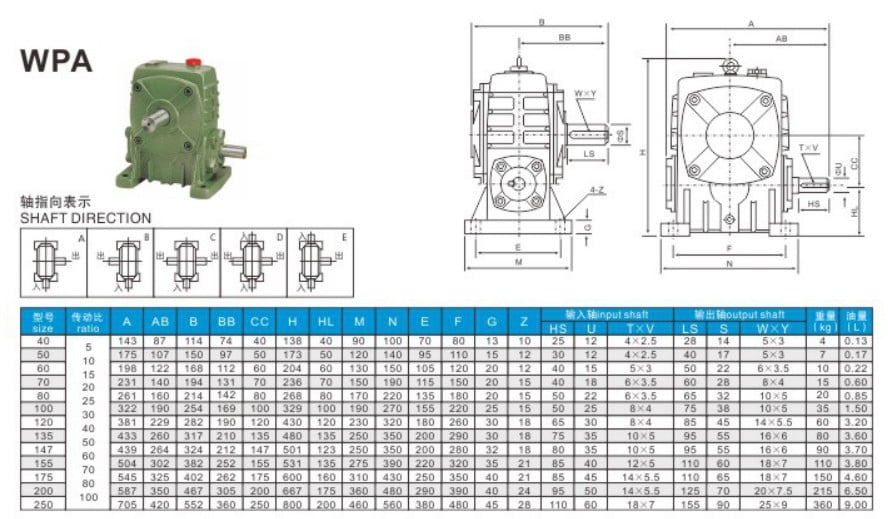

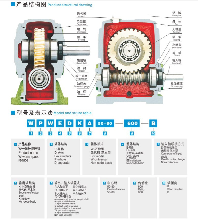
Certifications
Trade Shows
Packaging & Shipping
Packing Details : Standard carton/Pallet/Standard wooden case
Delivery Details : 15-30 working days upon payment

Company Information
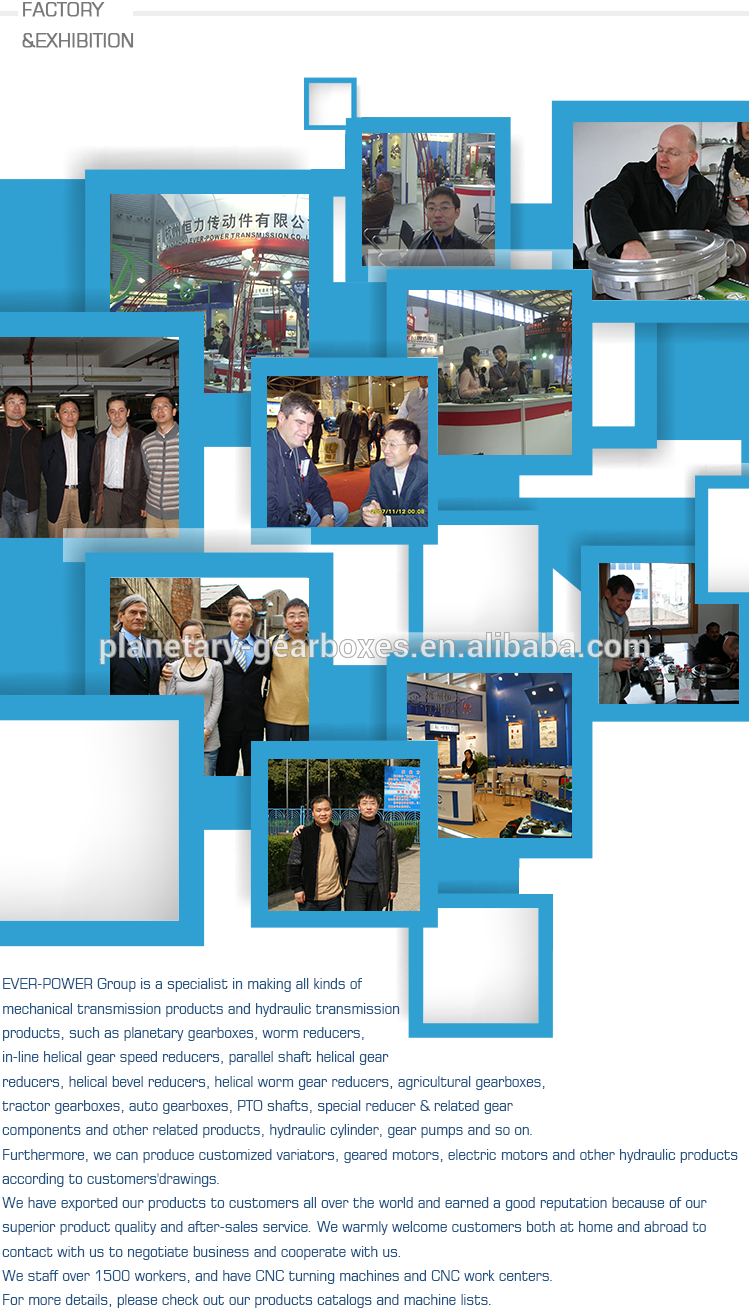
other series product
| Precision Planetary gearbox | Robot RV gearbox speed reducer |
| Custom made Non-standard Gearbox | UDL Series Variator |
| PYZ Series Helical Tooth Shaft Mounted Reducer | 8000 Series Cycloidal Reducer |
| SLT Series Spiral Bevel Gearbox | SLSWL Series Worm Screw Jack |
| SLP Series Planetary Reducer | SLH/SLB Series High Power Reducer |
| NMRV Series Worm Reducer | BKM Series Helical-hypoid Reducer |
| SLRC Series Helical Reducer | SLSMR Series Shaft Mounted Reducer |
| SLXG Series Shaft Mounted Reducer | X/B Series Cycloidal Reducer |
| SLR/SLF/SLK/SLS Series Helical Reducer |
Related Products
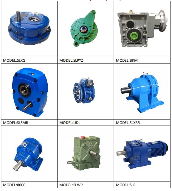
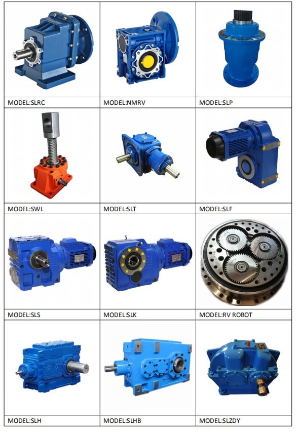
Contact